Continue to Site

Welcome to EDAboard.com

Welcome to our site! EDAboard.com is an international Electronics Discussion Forum focused on EDA software, circuits, schematics, books, theory, papers, asic, pld, 8051, DSP, Network, RF, Analog Design, PCB, Service Manuals... and a whole lot more! To participate you need to register. Registration is free. Click here to register now.

Cockcroft-Walton Voltage Multiplier Problem

Status
Not open for further replies.

jegues

Member level 3
Joined
May 29, 2011
Messages
58
Helped
0
Reputation
0
Reaction score
0
Trophy points
1,286
Activity points
1,915
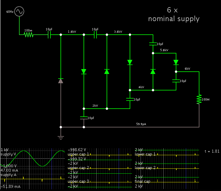
I have used PSCAD to simulate the circuit, but the use of any other circuit simulator should provide similiar results.

Attached is a picture of the circuit, and my PSCAD file.

First off, I build the circuit within PSCAD and input all of my source and component values. After doing so I have come across a number of problems, some of which I've attempted to fix and others for which I am clueless.

Problem 1: For my "Single Phase Voltage Source" I put in a voltage of 1kV because I desired a voltage with an amplitude that varies from +1kV to -1kV. When I had displayed the source output on the graph it looked at though the source was fluctuating between ~+/-1.4kV. Why is this, and how do I achieve my desired amplitude of 1kV? (For now I simply used trial and error to achieve a AC source of ~1kV amplitude, it required and input of ~0.72kV)

Problem 2: The circuit is not providing the correct output voltage, and I can't figure out why. I haven't changed anything within the diode settings except not to use the snubber circuitry. Furthermore, I measured V2p and V3p and found them to be identical waveforms to Vo. Ideally, Vo should sit somewhere around 2*n*Vs, where n is the number of stages. Since I used n=3 stages, I expect a voltage slightly below 6kV, but I am seeing a voltage of a mere 1kV. What is going on here?

Problem 3: Assuming I can get the circuit functioning properly, I want to make numerous measurements by varying one variables (i.e. f, C, load resistance etc...) and holding the others constant. Assume I had 3 different values for each variable that I wanted to test, this would leave me with 27 (3*3*3) circuits to reconfigure and measure. Is there a way where I can test all the different combinations of parameters while only building one circuit and have PSCAD tabulate the results for me? (Or something similar to make my life easier?)

Any insight/suggestions/comments/corrections on either of these problems would be greatly appreciated!

Thanks for your time!

Cheers!

PSCADQ1.JPGView attachment Cockcroft-Walton.zip
 
Last edited:

I would expect a waveform diagram with voltage and time units and an input voltage specification. According to the numbers mentioned in your post, the problem is using too low capacitance values related to 1 A output current. I guess, you didn't peform any calculations for reasonable component values?
 

This is a Villard multiplier. Two of them, arranged in mirror symmetry would go to make a Cockcroft-Walton type.

It has six stages (diode-capacitor cells) which should yield 6x your nominal AC supply.

* Your last (topmost) diode looks ghostly. I don't know what the simulator recognizes it as.

* There are cases where you must connect your load across the other set of capacitors, to obtain a smooth volt level on it. Otherwise you will see a large voltage swing on your load. It depends on the number of stages, and which capacitor is closest to the supply.

* I suggest you start with 10M or 100M as a load, to obtain the maximum output V. Notice your 1k load draws 1kW at 1 kV to begin with. It's easy to believe that amount of drain will not let your output V rise very high.

With regards to FvM these values were given to me by my professor and we did not cover a detailed analysis of the circuit in class either, we simply skipped to the results.

As suggested, I upped the size of my load resistor to 1MΩ so the capacitors are not bled dry due to the small time constant found when using a 1kΩ load.

My goal from this simulation was to compare the theoretical equations described in the table below to the simulation results.

See figure attached, EquationsWaveform.JPG

However from the simulation I measure a ΔV = 140V & 2δV = 38V, but from the Kuffel equation with all the capacitors all equal to C I calculate a ΔV = 26.4V & 2δV = 7.2V which is quite the discrepency.

Why is this?

Here is the resulting waveform from the simulation,

RL1M.JPG
 

This is a Villard multiplier. Two of them, arranged in mirror symmetry would go to make a Cockcroft-Walton type.
I don't think that this describes the general usage of the terms. The said symmetrical circuit is usually designated "full wave" CW multiplier, it's quite common to name the present circuit CW multiplier as well.

No complaints about the main thing, however.
 

I don't think that this describes the general usage of the terms. The said symmetrical circuit is usually designated "full wave" CW multiplier, it's quite common to name the present circuit CW multiplier as well.

Right, the nomenclature has become hard to nail down.

These articles agree with you. I have no basis to disagree.


http://en.wikipedia.org/wiki/Cockcroft–Walton_generator

However I have encountered several articles on the internet over the years. I see more than one name is connected to the multiplier in this thread. There is C-W and Villard and Greinacher.

For my own part, I find I need to give each of my circuit files a concise title which is informative.

So I've gotten in the habit of beginning with the simplest voltage doublers...
(a) one of which is based on the Villard cell (but which one source credits to Greinacher),
(b) the other based on a bridge of two half-wave supplies at opposite polarity (commonly credited to Greinacher but which one source calls the Delon doubler).

Then branching out to more complex multipliers, I add the half-wave parallel, full-wave parallel, series-parallel...

Then there is the type of supply, whether (a) AC sine waves, (b) pulsed DC alternating with high impedance, or (c) supply V alternating with zero ground... These all give different output levels.

So I have settled on a convention for giving names to my collection of voltage multipliers. The goal is to create names with quick recognizabilty, and which extend logically from the simple doublers as mentioned above. In regard to C-W multipliers, it is most frequently characterized as having several stages of Villard cells, mirrored above and below a zero ground. The developers for which it is named used it to boost a 200 kV supply to 800 kV. An article clarifies that it drew on the Greinacher design.

I have a hunch it will be impossible to create an orderly system of categories for all these varieties of voltage multipliers.

-----------------

Various web links in addition to those given above:

C-W history re early particle accelerators
shows a schematic not too different from the one in this thread


Wikipedia article
subheads include Villard, Greinacher, bridge, Dickson types
http://en.wikipedia.org/wiki/Villard_circuit#Villard_circuit

Jochen's high voltage page
mentions Greinacher, Villard, Villard cascade
http://www.kronjaeger.com/hv/hv/src/mul/

-----------------------------------------------------

- - - Updated - - -

----------------------------------------------------

However from the simulation I measure a ΔV = 140V & 2δV = 38V, but from the Kuffel equation with all the capacitors all equal to C I calculate a ΔV = 26.4V & 2δV = 7.2V which is quite the discrepency.

Why is this?

I don't know if current drain is factored into the equations, but a 10M load will allow the volt level to rise faster than a 1M load.

Even when the multiplier reaches an equilibrium (or maintenance) condition at over 5.9 kV, the 1M load draws bursts of a few hundred mA greater than the 10M load.

In case you would like to try measuring the results in a different simulation...

I am using Falstad's animated interactive simulator. It can export a link, below.
Click it and it will open the falstad.com/circuit website, load my schematic, and run it on your computer. (Click Alllow to load the Java applet.)

http://tinyurl.com/abm67qy

If you watch closely you will see the sequence in which the capacitors charge.

You can set the scope traces to show V or A, min and max readings, etc. Right-click on a trace and select what you want.

- - - Updated - - -


Hi Brad,

For some reason the link doesn't seem to be working when I click it. It brings up the Falstad page, but there is no other windows that prompt me to open up the actual circuit simulator. Is the link wrong?

Cheers!
 
Last edited:

Hi Brad,

For some reason the link doesn't seem to be working when I click it. It brings up the Falstad page, but there is no other windows that prompt me to open up the actual circuit simulator. Is the link wrong?

Cheers!

Sometimes it is quirky. If I previously opened the webpage, or if there was any hangup opening the simulator, I find I need to close all falstad.com windows, and try again.

Here is a screenshot of what just came up on my screen when I clicked the link:
https://tinyurl.com/abm67qy


Try cycling through all your browser windows. There may be a hidden dialog message in the background.

It is also necessary to have Java on your computer. Otherwise a notice should pop up saying it's absent, or that you need to go to a website to download it.

I finally got the circuit simulator to work! I also rebuilt the circuit on my android device using EveryCircuit, and the operation of the circuit is much more clear.

Using MATHCAD I compiled the theoretical results of Kuffel's and Maennel's equations and listed them alongside the simulation results, all of which are compiled in the table below,

EverythingTable.JPG

Is there anything from the table that jumps out at you?

One should note that I defined I for the theoretical case as,

\[I = \frac{2*n*V_{s,max}}{R_{L}}\]

This is appropriate for the theoretical calculations correct? (Obviously it can't be in reality because its is never the case that ΔV = 0 within the extents of my simulations)

I'm trying to get a reasonable numerical justification of not only how the circuit functions, but also which set of equations (Kuffel or Maennel) is more suitable in describing its output voltage sag and peak-to-peak ripple given certain circumstances.

Any comments?

Cheers!
 

Using MATHCAD I compiled the theoretical results of Kuffel's and Maennel's equations and listed them alongside the simulation results, all of which are compiled in the table below,

View attachment 85979

Is there anything from the table that jumps out at you?

Good work! A frame-by-frame analysis like this is the hallmark of a thorough approach. It can give you insights that the lazy-minded overlook.

I see how the columns are organized in groups of three: the simulation results, then Kuffel's, then Maennel's.

Across the board, the simulator figures are generally higher than the other two (with Kuffel's as the second highest).

The three agree more closely in the right half of the table, where C1 = 2 x C.

The faster the frequency, the smoother the ripple.
Raising the frequency can be as effective as using larger capacitors.
 

Status
Not open for further replies.

Similar threads

Part and Inventory Search

Welcome to EDABoard.com

Sponsor

Back
Top