Continue to Site

Welcome to EDAboard.com

Welcome to our site! EDAboard.com is an international Electronics Discussion Forum focused on EDA software, circuits, schematics, books, theory, papers, asic, pld, 8051, DSP, Network, RF, Analog Design, PCB, Service Manuals... and a whole lot more! To participate you need to register. Registration is free. Click here to register now.

[SOLVED] CMRR for a fully differential amplifier & Monte Carlo Simulations

Status
Not open for further replies.

Winny_Puuh

Junior Member level 1
Joined
May 1, 2013
Messages
17
Helped
0
Reputation
0
Reaction score
0
Trophy points
1,281
Visit site
Activity points
1,461
Hi guys,
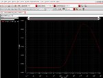
I am trying to simulate the CMRR of a fully differential telescopic amplifier. After having read quite a bit in the forum here I have come to a solution but I'm very unsure if I am really looking at the CMRR so I wanted someone who knows more than me to confirm it (see screenshots).
And actually I wanted to see the CMRR in a Monte Carlo Simulation but do I have to look at the DC value then or at a special frequency? My first results make me think I did sth. wrong cause the CMRR goes from -2,88dB to -75 dB... that can't be right...
Thanks for any help,
Winny
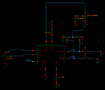
schematic_cmrr.pngcmrr.png
 

Hi!

The CMRR is how the output can reject the input common mode. If your OpAmp is perfect (no mismatch) then the CMRR should be very low (-400dB). But, if a mismatch occurs, for example between the size of the transistors in your input differential pair, then with a common voltage at the inputs you should get a differential voltage at the output.
For your analysis, do an AC simulation (ie from 1Hz to 10GHz). Put a common voltage at the inputs (like you did) with a DC offset and sweep the AC. (You can change the DC value to see how the CMRR can vary). And you should see the output differential mode (VoutMD = VinMD x Gd + VinMC x GMC). As VinMD is Zero, you'll know the GMC, then deduce the CMRR as you already know the gain of your OpAmp.

Before an MC sim, you can first modify the input transistors (change for example the W of the inverted input by a factor of 1%) and run the simulation. Once you get it, you can try with monte carlo.

Hope it helps!
 
Last edited:
Hi, thank you for your reply =) so what you say is, my CMRR for let's say 1 Hz would be 40 (which is my closed loop gain of the amplifier) - (-194 dB) = 234 dB without mismatch at first? Do I have to take the closed-loop or open loop gain for calculating the CMRR? Then I changed the dimensions of one input transistor as you said and my GMC looked totally different but I hope that's normal. And what frequency do I choose for the GMC value, for my calculations I just chose 1 Hz but is there a more intelligent way?
 

Re: CMRR for a fully differential amplifier & Monte Carlo Simulations

my CMRR for let's say 1 Hz would be 40 (which is my closed loop gain of the amplifier) - (-194 dB) = 234 dB

The CMRR is the gain in differential mode of the OpAmp in OPEN LOOP divided by the common mode gain of the OpAmp. On your plot, you have only the Out2+, as it's a fully differential OpAmp, Vout = Vout+ - Vout-. If it's perfect, the common mode gain should be 0. (which correspond to -400dB, the minimum of the simulator)

Then I changed the dimensions of one input transistor as you said and my GMC looked totally different but I hope that's normal.

Sure! The CMRR is greatly affected by the input mismatch!

And what frequency do I choose for the GMC value, for my calculations I just chose 1 Hz but is there a more intelligent way?

Good question... it may depends on your frequency of interest. At 1Hz you have the CMRR in "static". This corresponds to the value you can read on datasheets. With an AC simulation, you have an idea on how it can degrade.
 
Thank you, you really helped me! Hope I will be able to go on with the simulations now ;)
 

Status
Not open for further replies.

Part and Inventory Search

Welcome to EDABoard.com

Sponsor

Back
Top