Continue to Site

Welcome to EDAboard.com

Welcome to our site! EDAboard.com is an international Electronics Discussion Forum focused on EDA software, circuits, schematics, books, theory, papers, asic, pld, 8051, DSP, Network, RF, Analog Design, PCB, Service Manuals... and a whole lot more! To participate you need to register. Registration is free. Click here to register now.

CMOS Crystal Oscillator Circuit

Status
Not open for further replies.

e-music

Member level 5
Joined
Dec 29, 2017
Messages
84
Helped
0
Reputation
0
Reaction score
0
Trophy points
6
Activity points
1,065
Hi,

If this is not the place to ask this, please move at will!

The following is a CMOS Crystal Oscillator Circuit that generates a square wave:

CMOS_Oscillator.gif

I will use this circuit to supply the clock needed for a legacy device that accepts clocks in the range of 10~40 Mhz. Is this the best way to do it? What is the formula used to calculate C, R1, and R2 for a 40 Mhz crystal?

Regards,

Zaher
 

Hi,

Is this the best way to do it?
It is one way to do it.
We can´t say if it´s the "best" because "best" - without saying in which regard - is meaningless.
It could be the "best" reagrding: cost, size, availability, current consumption, jitter, temperature stability ..... and many other.


What is the formula used to calculate C, R1, and R2 for a 40 Mhz crystal?
The circuit mainly depends on the used XTAL. It´s datasheet tells you how to use it.
Usually the manufacturer provides additional information like application notes, design notes, example circuits, online calculators... and so on.
--> Thus visit the website and look for information.

Klaus
 

The standard CMOS crystal oscillator uses an unbuffered inverter rather than ST gate. The author also makes his life easy by not specifying the logic family. If the circuit should work with ST gates, very unlikely at 40 MHz.

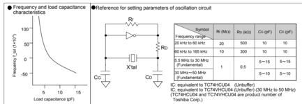
I'd rather trust manufacturer application notes like below quoted from Epson.


20220925_091831.png


--- Updated ---

Where did you copy the post #1 schematic? I guess it has been edited by someone who doesn't understand circuit oscillation condition.
 
Last edited:
I don't think you want a Schmitt inverter. All the CMOS XOs
I've seen, seem to want single stage inverters with no
hysteresis.
 
The standard CMOS crystal oscillator uses an unbuffered inverter rather than ST gate. The author also makes his life easy by not specifying the logic family. If the circuit should work with ST gates, very unlikely at 40 MHz.

I'd rather trust manufacturer application notes like below quoted from Epson.


View attachment 178685


--- Updated ---

Where did you copy the post #1 schematic? I guess it has been edited by someone who doesn't understand circuit oscillation condition.
Thank you. That was very helpful. The original circuit has been copied from:
--- Updated ---

Hi,


It is one way to do it.
We can´t say if it´s the "best" because "best" - without saying in which regard - is meaningless.
It could be the "best" reagrding: cost, size, availability, current consumption, jitter, temperature stability ..... and many other.


The circuit mainly depends on the used XTAL. It´s datasheet tells you how to use it.
Usually the manufacturer provides additional information like application notes, design notes, example circuits, online calculators... and so on.
--> Thus visit the website and look for information.

Klaus
Thank you!
--- Updated ---

This might help -


Regards, Dana.
--- Updated ---

40 Mhz will require some very fast G elements :


Above << 10 nS Tpd. Not sure of their gain.....


Regards, Dana.
Thank you Dana. That was an interesting read!

Zaher
--- Updated ---

I don't think you want a Schmitt inverter. All the CMOS XOs
I've seen, seem to want single stage inverters with no
hysteresis.
Right. I have several circuits/implementations that all use an inverter. However, I don't know why they used schmitt inverter on this one. Anyways, most implementations I come across use two inverter stages.
 
Last edited:

Unless you are requiring large numbers of the oscillator circuit it is always better to buy a oscillator module particularly if the frequency required is above 8Mhz or so.
 

Unless you are requiring large numbers of the oscillator circuit it is always better to buy a oscillator module particularly if the frequency required is above 8Mhz or so.
No, not relatively that large number. Do you have any reference for these modules, datasheet, PN, etc.
--- Updated ---

By the way, what is the difference between supplying the clock (16~40 Mhz)from the above crystal oscillator circuit vs the output of MCO pin in the STM32. And in case of the latter, is there any need for inverter, amplification, or caps?
 
Last edited:

Hi,

did you try an internet search "xtal oscillator" on your own?

of MCO pin in the STM32. And in case of the latter, is there any need for inverter, amplification, or caps?
There are hundreds of different ST32 .... We don´t know which one you refer to.
Each one comes with a datasheet.
But even if we knew the exact type, it´s important that you read the datasheet first.
There usually is a whole section about the clock input.

Klaus
 

Hi,

did you try an internet search "xtal oscillator" on your own?


There are hundreds of different ST32 .... We don´t know which one you refer to.
Each one comes with a datasheet.
But even if we knew the exact type, it´s important that you read the datasheet first.
There usually is a whole section about the clock input.

Klaus
Klaus,
Be certain that I never rush to ask questions without doing my homework and research on my own. And I'm not always asking questions for every tiny issue I face, unless a clear and definite answer was not available.
For this one, I really didn't ask about the clock input of my MCU. Please refer to the OP and read it carefully before you reply. You always take a portion of my input, reply it, and ignore the main issue. I used to that! :))
Well, MCO = Master Clock Output. So, here I was referring to outputting the clock signal off my MCU, and not the opposite. The original CMOS crystal oscillator circuit is used to supply clock for a legacy device. I just asked if I used the MCO of my STM32, and I did specify the frequency range so I doubt the MCU series matters a lot here, what is the difference for the clock signal generated. Well, these details could be easily ignored by most designers. I thought it would be better to ask.
 

Hi,

fair enough.

I really didn't ask about the clock input of my MCU
Yes, my mistake. I wrote "input" while I meant the complete oscillator circuit. Yes, I am not perfect and never wrote and never meant it to be.
All the rest of my post exactly refers to your problem.
It´s still a question of thechnical specification of the one IC´s output and the other´s IC´s input.
Still my way is to read the datasheets. (we still don´t have any information of both involved ICs. Not our fault.)
It´s my way to read datasheets. I do it every day. If you have a better way, then please tell us. I still want to learn.

Please refer to the OP and read it carefully before you reply. You always take a portion of my input, reply it, and ignore the main issue.
So there exactly are two questions in your intial post:

* About the "best"
Without knowing what the "best" is for you .. the question can not be answered. I asked questions about your "best" requirements but you did not answer them.

* about the formula:
I gave you the exact way that I learned to use in my several decades of electronics development experience.
Nobody is able to give you a more detailed answer because - again - you missed to give detailed information.
I don´t tell stories, if I need detailed information I do it exactly like written. Why should I recommend you a different way?
And still: It´s just a recommendation. It´s on you whether you use this or not.

Until now we don´t know what XTAL you use, what supply voltage you use, what "legacy device" you want to supply and so on. All things that need to be considered. No story, just fact.

So in my opinion I used every single information you gave to support you with the best available answer.

***
If you miss to give clear informations, then please don´t blame it on others.
Missing technical informations, missing datasheet links, missing links to websites, missing to tell "what homework you did" ....
If you can´t stand to be asked for "doing an internet research" ... then please tell us that you did, what you expected to find and what you missed to find.
If you think asking for information is a bad thing, then what did you do on post#1?
Or .. are you allowed and we not? Master - servant?

If you jump form one topic ("best" and "formula" of the given XTAL oscillator) to another within a thread ... again: don´t blame it on us.

I´m not perfect. I know.
Maybe you are perfect. I also don´t know.

Klaus
 

No, not relatively that large number. Do you have any reference for these modules, datasheet, PN, etc.
--- Updated ---

By the way, what is the difference between supplying the clock (16~40 Mhz)from the above crystal oscillator circuit vs the output of MCO pin in the STM32. And in case of the latter, is there any need for inverter, amplification, or caps?

The datasheet (I looked at) has no drive specs for MCO, but does show application
schematic for using it to drive a 10/100 PHY at 26 Mhz. So my guess is a single low
C gate load might be OK, but large C load probably out. I would check with a ST field
engineer on this to make sure.

Using this, derived from PLL, only other issue seems jitter, which datasheet seems to indicate
pretty low.


Regards, Dana.
 

Compared to a crystal oscillator, jitter of STM32 PLL is large and potentially unsuitable for applications that need a clean clock source, e.g. RF communication or signal generators but sufficient for most general digital purposes.
--- Updated ---

MCO pin shares GPIO static and dynamic specifications, in so far the datasheet leaves no open questions.
 

Confirm this sure looks like it falls under GPIO specs, and jitter measured :

1664296929396.png


Signal digital generators at 100 Mhz around 200+ ps, Rigol stuff. DDS based arbitrary type.


Regards, Dana.
 
Last edited:

Compared to a crystal oscillator, jitter of STM32 PLL is large and potentially unsuitable for applications that need a clean clock source, e.g. RF communication or signal generators but sufficient for most general digital purposes.
--- Updated ---

MCO pin shares GPIO static and dynamic specifications, in so far the datasheet leaves no open questions.
Thank you very much. That's exactly what I wanted to know, and that's exactly what I call a very helpful reply.
--- Updated ---

Confirm this sure looks like it falls under GPIO specs, and jitter measured :

View attachment 178743

Signal digital generators at 100 Mhz around 200+ ps, Rigol stuff. DDS based arbitrary type.


Regards, Dana.
Thank you Dana. That was very helpful, too! So, basically for lower frequencies, jitter is minimal.
--- Updated ---

Hi,

fair enough.


Yes, my mistake. I wrote "input" while I meant the complete oscillator circuit. Yes, I am not perfect and never wrote and never meant it to be.
All the rest of my post exactly refers to your problem.
It´s still a question of thechnical specification of the one IC´s output and the other´s IC´s input.
Still my way is to read the datasheets. (we still don´t have any information of both involved ICs. Not our fault.)
It´s my way to read datasheets. I do it every day. If you have a better way, then please tell us. I still want to learn.


So there exactly are two questions in your intial post:

* About the "best"
Without knowing what the "best" is for you .. the question can not be answered. I asked questions about your "best" requirements but you did not answer them.

* about the formula:
I gave you the exact way that I learned to use in my several decades of electronics development experience.
Nobody is able to give you a more detailed answer because - again - you missed to give detailed information.
I don´t tell stories, if I need detailed information I do it exactly like written. Why should I recommend you a different way?
And still: It´s just a recommendation. It´s on you whether you use this or not.

Until now we don´t know what XTAL you use, what supply voltage you use, what "legacy device" you want to supply and so on. All things that need to be considered. No story, just fact.

So in my opinion I used every single information you gave to support you with the best available answer.

***
If you miss to give clear informations, then please don´t blame it on others.
Missing technical informations, missing datasheet links, missing links to websites, missing to tell "what homework you did" ....
If you can´t stand to be asked for "doing an internet research" ... then please tell us that you did, what you expected to find and what you missed to find.
If you think asking for information is a bad thing, then what did you do on post#1?
Or .. are you allowed and we not? Master - servant?

If you jump form one topic ("best" and "formula" of the given XTAL oscillator) to another within a thread ... again: don´t blame it on us.

I´m not perfect. I know.
Maybe you are perfect. I also don´t know.

Klaus
Klaus,

For goodness sake, no one claims to be perfect, and I presume everyone has the passion to learn something new because it's impossible for us, human beings, to have it all. So, unfortunately, I don't have a better way to learn and I'm not here to teach anyone. For me personally, I keep about 20 tabs open of datasheets, app notes, ref designs, and code snippets, as long as my computer is running. Of course, let alone dozens of printed material and books that surround me.
I just don't see why you take everything, every tiny bit of my words to the extreme. About the best, about the formula, about the cost, volume, why you need it, what is your target application, how old are you?? Guess what, thank you very much for not asking certain other questions! :))
WHat started as a simple question that could be answered in couple of words, ended up as a lengthy lecture of alleged accusations. Could you please show me where I blame someone here?? "Master - Servant"? To that extent? Who said asking for information is a bad thing? And don't you think it's obvious when someone posts a question here that this someone needs information? And if you consider yourself a "servant" when replying someone's question, why not stick with your datasheets doing something for yourself instead of wasting your precious time on discussion forums?
Could you please compare replies received from other members to yours? That's really a waste of time and energy. Just for your convenience, I'm not big fan of discussion forums and wasting my time to prove me/you right/wrong. I guess that's your approach, because I'm pretty sure if God himself made a post here, you will find a way to refute. Just FYI, over the past 10 years, and from my own experience asking a very limited number of questions at certain discussion forums, I used to encounter two types of replies.
1- When you provide plenty of details about the application, what you want to do, and how you want it to be done, the replies you would get look like the following: "You want us to do it for you? We are sorry, but we are not working for you. Please read the datasheet, do your homework, and do it yourself"
2- You provide little detail about the target application with only questions about a specific area of concern, the replies would be similar to that of Klaus: "You didn't tell us what is the MCU used, what is the ASIC interfaced, voltage rating, frequency, why you want to do it, what do you mean by best, what do you mean by good, you didn't tell us what homework you did, where did you find this info, ". Not tired yet? Ohhh, that took a considerable part of my time. I wonder if our CEO here wants to fire someone today??
In fact, I would blame it all on me. I shouldn't ask/post in the first place. Anyways, I would like to thank you all for your helpful replies, thanks for Dana, her reply in another thread introduced me to some powerful devices in the Cypress/Infineon ecosystem that I wasn't aware of. This would be my last reply here. I'm so sorry, but I'm not willing to waste more time and energy in replying to Klaus because I don't think I have a fraction of fraction of the energy and capability he has for this endless debate/challenge. I will go back to my datasheets, to my messy desk, to my PCBs and equipment. Things used to work out for me for over 10 years now with minimal input/help from anyone. I can give up those questions and spend more of my time doing it all myself.
Now, please terminate my account and remove all of my data here. I will not use this forum anymore, I promise!
 
Last edited:

Status
Not open for further replies.

Part and Inventory Search

Welcome to EDABoard.com

Sponsor

Back
Top