yixiusky
Member level 2
loop gain cmfb
I would like to ask one question:
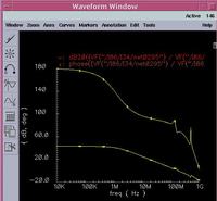
when i check the stability of CMBF loop. There is peak shows in both loop gain and phase margin plot. I can not know the reason. Could you help me ?
thank you very much
 [/img]
I would like to ask one question:
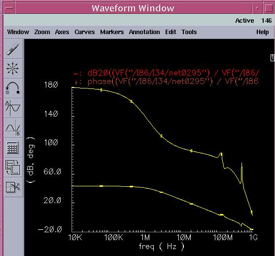
when i check the stability of CMBF loop. There is peak shows in both loop gain and phase margin plot. I can not know the reason. Could you help me ?
thank you very much
 [/img]