Continue to Site

Welcome to EDAboard.com

Welcome to our site! EDAboard.com is an international Electronics Discussion Forum focused on EDA software, circuits, schematics, books, theory, papers, asic, pld, 8051, DSP, Network, RF, Analog Design, PCB, Service Manuals... and a whole lot more! To participate you need to register. Registration is free. Click here to register now.

closed loop gain accuracy

Status
Not open for further replies.

Junus2012

Advanced Member level 5
Joined
Jan 9, 2012
Messages
1,552
Helped
47
Reputation
98
Reaction score
53
Trophy points
1,328
Location
Italy
Visit site
Activity points
15,235
Hello

during the design of the Op-amp we consider only the DC gain and we said it is our gain. but as you all know that this gain is decreasing very fast with frequency so how we will sure about the accuracy of the closed loop op-amp at littoral high frequently where the gain here is not so hign

take the example of the unity gain buffer to explain this issue please

Regards
 

as a rule of thumb for all resistive negative feedback Opamp gain blocks Gain x Bandwidth is constant. you can find this value in datasheet of the opamp you are using; its unit is frequency unit (MHz) since gain has no unit!
for example if Gain Bandwidth of the opamp is 1 MHz and you have designed an amplifier with a gain of 10, you will have 100KHz Bandwidth, i.e. gain is 10 from DC to 100KHz and after that will decrease. also for unity gain amplifier or buffer (Gain=1) the bandwidth would be 1MHz, i.e gain will be 1 from DC to 1MHz.
therefore for high frequency applications you should look for opamps with sufficient GBW. of course in high frequency design other issues like series inductance of the resistors and input capacitance of the opamap must be considered to prevent unwanted oscillations or instabilities.

BEST
 
I don't exactly understand what you're up to? If you know the OP open loop gain characteristic, you can calculate the closed loop gain pretty accurately.

For some applications, e.g. video amplifiers, it's usual to specify gain and phase errors considerably below the -3 dB bandwidth limit.
 

I don't exactly understand what you're up to? If you know the OP open loop gain characteristic, you can calculate the closed loop gain pretty accurately.

Yes, that`s correct. Using the classical formula from Black you can find the closed-loop gain even for rather small open-loop gain values (for example, as it s done for simple transistor amplifiers).
With other words - the simplified formulas involving the external resistors only are NOT applicable anymore.
However, you have to know that in this case some phase deviations between input and output occur.
On the other hand, I suppose in his question Junus is referring to the case where the simplified formulas can be used. In this case, thae answer in post#2 applies.
Finally, the following hint: The simplified formulas apply as long as the loop gain T(jw) is large enough (T(jw)>>1). The mentioned 3dB threshold is identical to the case T(jw)=1 (0dB).
 

Hello friends
thanx a lot for your kind replies.

I attached here two articles which can be more clear than my post
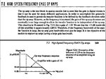
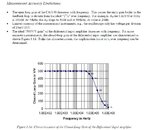
I understand from you all the relationship between the gain and the bandwidth, for me I am thinking that this relationship is not valid when t he open loop gain drops because the closed loop gain will not be further independent on the Op-amp characteristics. for example, usually in the closed loop op-amp we can say that the gain of the inverting amp is R2/R1 or the gain of the buffer is unity but this under condition of the open loop gain AOL >= 60db. when the open loop gain drop with frequency we cannt say that it still R2/R1 or unity gain

please have a look of the attachments

thank you in advance
 

Attachments

  • gbw.JPG
    gbw.JPG
    109.2 KB · Views: 150
  • gbw2.JPG
    gbw2.JPG
    113.3 KB · Views: 143

...or the gain of the buffer is unity but this under condition of the open loop gain AOL >= 60db. .........

OK - that´s correct (may be, one can define the limit at AOL>=40...50 dB, but that`s not the point).
However, please note that the limit you have mentioned (60 dB) applies to the unity-gain buffer application only!
Because in this case the loop gain T(s)=(buffer gain*AOL)=60 dB.

For other application with gain values>0 dB the limit of 60 dB applies to the loop gain - and NOT to the AOL of the opamp alone.
See my last post.
In this context, I point to the fact that the first attachement you have shown contains also the loop gain response vs. frequency.
It is simply the AOL curve - however, referred to another frequency axis, which is now the 20 dB line.
 

I am really sorry if still I am not getting it, so I would ask you according to the left image (part 7.2). as you see that up to wa the AOL is very high so we can apply the closed loop principles. after wa and specially near to w-3db of the closed loop response the AOL is now very low so how we still keep the same expression of the ACL of the closed loop gain in this area as like the same ACL in the low frequency region. I think my second image is describing my problem more clear

Thank you a lot


OK - that´s correct (may be, one can define the limit at AOL>=40...50 dB, but that`s not the point).
However, please note that the limit you have mentioned (60 dB) applies to the unity-gain buffer application only!
Because in this case the loop gain T(s)=(buffer gain*AOL)=60 dB.

For other application with gain values>0 dB the limit of 60 dB applies to the loop gain - and NOT to the AOL of the opamp alone.
See my last post.
In this context, I point to the fact that the first attachement you have shown contains also the loop gain response vs. frequency.
It is simply the AOL curve - however, referred to another frequency axis, which is now the 20 dB line.
 

I am really sorry if still I am not getting it, so I would ask you according to the left image (part 7.2). as you see that up to wa the AOL is very high so we can apply the closed loop principles. after wa and specially near to w-3db of the closed loop response the AOL is now very low so how we still keep the same expression of the ACL of the closed loop gain in this area as like the same ACL in the low frequency region. I think my second image is describing my problem more clear
Thank you a lot

Well, I think you are able to understand my comment only if you know
* the formula from Black (and it`s meaning): Acl=Aol*a/(1+Aol*b) with b=feedback factor
* the role of the loop gain T=Aol*b

What is the remaining question?
 

Well done LvW
now according to the expression ACL = AOL / (1+b*AOL), consider b =1 for the unity gain buffer and take these values of AOL with respect to frequency from the open loop characteristics :

1. AOL = 80dB at f=0 Hz
2. AOL = 75dB at f=1 KHz
3. AOL=50 dB at f=10KHz
4.AOL =20 dB at f=50 KHz
5.AOL = 0dB at f= 1 MHz where the value of 1MHz is the GBW (from the open loop char)

when you go now to substitute these values in the ACL = AOL / (1+b*AOL), you will find that we get a unity gain result only till 50 KHz, in the above region of frequency it will deviate severely from unity.
While it supposed from any literature that the bandwidth of the buffer is extended till the GBW of the op-amp with gain equal to one which I show you it is not one till the GBW

hope this will be my last question :)

Well, I think you are able to understand my comment only if you know
* the formula from Black (and it`s meaning): Acl=Aol*a/(1+Aol*b) with b=feedback factor
* the role of the loop gain T=Aol*b

What is the remaining question?
 

Yes you are correct. The closed loop gain goes down an the loop gain(product of opamp gain and feedback factor) goes down and the closed loop gain will not be unity at the GBW. It can be seen that the bandwidth of the buffer is the same as the unity loop gain frequency. Loop gain, I repeat, is the product of the opamp gain and the feedback factor. Consider the case at unity loop gain frequency. At this frequency, the closed loop gain would be 0.5 which is - 3 dB. Hence it is said that the bandwidth of the closed loop amplifier is the same as unity loop gain frequency.
 

For the interpretation of ACL = AOL / (1+b*AOL) you should consider that b and AOL are both complex numbers. Assuming a first order AOL characteristic, the phase will be -90° in the region of interest, means b and AOL add geometrically. Thus for b=1 and AOL of 20 dB, the ACL error will be only 0.5%, not 9% as you might assume.
 
  • Like
Reactions: LvW

    LvW

    Points: 2
    Helpful Answer Positive Rating
...........
when you go now to substitute these values in the ACL = AOL / (1+b*AOL), you will find that we get a unity gain result only till 50 KHz, .

No, I don`t think so. Why 50 kHz? Why not 10 kHz or 100 kHz?
For a finite AOL we always are somewhat below 0 dB. The only question is how much error (deviation from 0 dB) you can tolerate.
By the way - also the assessment of -3dB at w=GBW applies under the assumption that AOL is a single pol model.
For real amplifiers with a second pole in the vicinity of the 0dB-crossing frequency there will be a slight peaking in the magnitude response in this frequency region.
 
because if you subsidence the value i assumed of AOL at 50 KHZ or 10 or 100 KHZ you will not get unity gain result


No, I don`t think so. Why 50 kHz? Why not 10 kHz or 100 kHz?
For a finite AOL we always are somewhat below 0 dB. The only question is how much error (deviation from 0 dB) you can tolerate.
By the way - also the assessment of -3dB at w=GBW applies under the assumption that AOL is a single pol model.
For real amplifiers with a second pole in the vicinity of the 0dB-crossing frequency there will be a slight peaking in the magnitude response in this frequency region.
 

The gain error at 50 kHz is about 0.01 dB. I guess, you'll have serious difficulties to measure it.
 

Status
Not open for further replies.

Part and Inventory Search

Welcome to EDABoard.com

Sponsor

Back
Top