Continue to Site

Welcome to EDAboard.com

Welcome to our site! EDAboard.com is an international Electronics Discussion Forum focused on EDA software, circuits, schematics, books, theory, papers, asic, pld, 8051, DSP, Network, RF, Analog Design, PCB, Service Manuals... and a whole lot more! To participate you need to register. Registration is free. Click here to register now.

Class-E oscillator claims near 100% measured efficiency

Status
Not open for further replies.

neazoi

Advanced Member level 6
Joined
Jan 5, 2008
Messages
4,123
Helped
13
Reputation
26
Reaction score
15
Trophy points
1,318
Location
Greece
Activity points
36,955
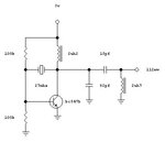
I have build and tested the attached circuit (image), from the PDF file which claims to be a near 100% efficient class-e crystal oscillator. However the efficiency I measure seems very bad.

First of all, shall I measure it on 50R or on 1Meg?
I am confused about my measurements on the scope, with VPP and with the its FFT, I may be doing something wrong.
 

Attachments

  • J2011F.pdf
    4.6 MB · Views: 106
  • 100.JPG
    100.JPG
    16.6 KB · Views: 137

1 Meg but I'm not sure what you are trying to measure. In this context the load is power delivered through the 2.7uH inductor, it isn't intended to drive further circuitry. The 2.7uH coil is essentially the primary of a transformer that couples magnetically to a medical implant.

Brian.
 
  • Like
Reactions: neazoi

    neazoi

    Points: 2
    Helpful Answer Positive Rating
They don't show waveforms for the circuit with the ~100% supposed efficiency. But they do show waveforms for a higher power version of the circuit, and they look very poor (and they don't state the efficiency of that circuit, it's likely <80%). Overall everything here is pretty questionable.
 
  • Like
Reactions: neazoi

    neazoi

    Points: 2
    Helpful Answer Positive Rating
I really wonder what's the purpose of this thread. You can surely improve efficiency by forcing the oscillator operation point towards "class-E". Making a near "100 %" single transistor oscillator seems pretty useless to me, even if it would be possible. You get better control of frequency, output power and maximum efficiency in a multi stage design in any case.


First of all, shall I measure it on 50R or on 1Meg?
An output stage has to be adapted for the actual load impedance, the question suggests that you have presently no clue what you want to achieve with the circuit.
 
  • Like
Reactions: neazoi

    neazoi

    Points: 2
    Helpful Answer Positive Rating
First of all, shall I measure it on 50R or on 1Meg?
Neither one. If you want to follow the paper.
Reading a few lines you can realize that they have measured the efficiency of the "oscillator" without any load. That is why very high efficiency is measured, unfortunately is pointless, as FvM mentioned.

Besides, the paper is overall doubtful.
PAGE 10, referring to fig 8:
The power used by this circuit is 77mW (18.9dBm), which is determined
by multiplying the supply voltage with the r.m.s. value of the total current.
I hope it is a typo.
 
  • Like
Reactions: neazoi

    neazoi

    Points: 2
    Helpful Answer Positive Rating
Neither one. If you want to follow the paper.
Reading a few lines you can realize that they have measured the efficiency of the "oscillator" without any load. That is why very high efficiency is measured, unfortunately is pointless, as FvM mentioned.

Besides, the paper is overall doubtful.
PAGE 10, referring to fig 8:

I hope it is a typo.

I saw on the net this "keychain transmitter" and I thought a better design could be made in a keychain emergency shortwave transmitter. First thought of course was to include a battery in it, but the overall thing has to be small, so efficiency does matter if one wants to achieve max range.
So I started to look for class-E oscillators, because the space and available DC power is very limited. I may be in the wrong path, so any thoughts are appreciated.

- - - Updated - - -

1 Meg but I'm not sure what you are trying to measure. In this context the load is power delivered through the 2.7uH inductor, it isn't intended to drive further circuitry. The 2.7uH coil is essentially the primary of a transformer that couples magnetically to a medical implant.

Brian.

No medical implant in my case, just an emergency transmitter very small sized and as much powerful as possible. This calls for a class-E circuit I guess. I am looking for low voltage designs too, as single cell batteries would be convenient with it I guess.
If I could find a 1.5v crystal oscillator that can provide quite a few 10s or 100s mW of output power, this would be all that would be needed actually.
 

I wouldn't worry about class-E or efficiency in that case, concentrate on output purity and being able to modulate it sensibly. A carrier alone is highly unlikely to be of much use unless it can be picked out from all the other carriers across the spectrum.

Also beware of "100s mW" from a crystal oscillator. A low power crystal oscillator and conventional PA to boost it's output to 100mW+ would be more efficient, particularly when you need to match it to some kind of antenna.

Brian.
 

I saw on the net this "keychain transmitter" and I thought a better design could be made in a keychain emergency shortwave transmitter.
Not sure what sort of modulation is used for "emergency shortwave" transmission. Class E would be fine for something like OOK, FSK, PSK, etc. Otherwise you'll want to stick with a linear output stage like class A or B.
 

Not sure what sort of modulation is used for "emergency shortwave" transmission. Class E would be fine for something like OOK, FSK, PSK, etc. Otherwise you'll want to stick with a linear output stage like class A or B.

He uses CW (OOK).

I have found a very interesting circuit, which needs no battery at all!
https://www.youtube.com/watch?v=guIRbb8ETGg
Although this would not fit into a key chain...
Now I am starting to think of a tony pneumatic power generator, maybe a tiny fanned motor generator would be easier to produce power. Something like blowing inside a straw, with a tiny fan-magnet attached at the air output. I am looking for such designs on the net but I have no success.
Any ideas are welcome.
 

Status
Not open for further replies.

Part and Inventory Search

Welcome to EDABoard.com

Sponsor

Back
Top