Continue to Site

Welcome to EDAboard.com

Welcome to our site! EDAboard.com is an international Electronics Discussion Forum focused on EDA software, circuits, schematics, books, theory, papers, asic, pld, 8051, DSP, Network, RF, Analog Design, PCB, Service Manuals... and a whole lot more! To participate you need to register. Registration is free. Click here to register now.

Class E amplifier design

Status
Not open for further replies.

uoficowboy

Full Member level 3
Joined
Apr 4, 2009
Messages
169
Helped
6
Reputation
12
Reaction score
5
Trophy points
1,298
Location
Seattle, Wa, USA
Activity points
2,964
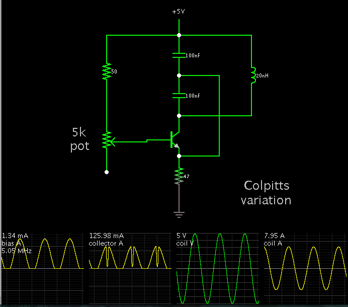
For a resonant wireless charging system, I am looking at using a Class E driver. I've played around with some circuits on the web, and played around with values in LTSpice quite a bit - and there are a couple things that have really bothered me:

1. I have yet to find any clear derivation of values for the capacitors and inductors. Heck, I haven't even really found formulas - most papers point to specific design tools.
2. With the spice simulation that I've been using, I have both positive and negative current flowing through my switch. The waveform looks about what I would expect it to look like, but the negative current is somewhat disturbing. When I add more resistance in series with the tank inductor the current in the switch will become almost entirely positive. But in my desired system I really just want to push/pull tons of current through the tank inductor so resistance should be very small. I'm thinking I may just need to add back to back FETs (instead of using a single FET) - but would love to hear if anybody else has encountered this.
3. I am not clear on how to modulate the amplitude of the current in the tank inductor (L2). If I change the duty cycle of my PWM that is driving my switch, the tuning gets thrown completely off. I could change the supply voltage, but surely there is a better way? I do not need fast modulation - it is only so that I can respond appropriately to coils changing position with respect to each other.

Thank you in advance!!

Note: I have included a .JPG showing my simulation as well as a LTSpice file. I had to change the extension on the ltspice file from .asc to .txt. Please change it back to .asc after downloading it and you should be able to run it easily.
 

Attachments

  • ClassEProblems.jpg
    ClassEProblems.jpg
    159 KB · Views: 119
  • Class E Test 2.txt
    1.6 KB · Views: 65
Last edited:

Why are you worrying about negative MOSFET drain current? It's just normal operation of the present circuit (due to parallel C).
 

Why are you worrying about negative MOSFET drain current? It's just normal operation of the present circuit (due to parallel C).
I hadn't seen significant negative current in the waveforms that I looked at of other circuits, but I believe the difference there is unloaded vs loaded operation.

My biggest concern right now is figuring how to modulate the amplitude of this.
 

But in my desired system I really just want to push/pull tons of current through the tank inductor so resistance should be very small.

You may wish to consider LC oscillator circuits such as Colpitts, Clapp, Hartley.

They oscillate at a frequency which is automatically the resonant frequency.

Notice that the more current you want going through the coil, the more inertia the LC tank will have, and the more care will be needed to adjust for desired operation.
I do not think any of those topologies are really designed to put large amounts of current into the LC tank, right? I am looking to put multiple amps into a microhenry inductor, and maintaining efficiency is key to making this thing not blow up.
 

I do not think any of those topologies are really designed to put large amounts of current into the LC tank, right? I am looking to put multiple amps into a microhenry inductor, and maintaining efficiency is key to making this thing not blow up.
The AC current through the "tank" incuctor will be set by the inductance value and respectively low. The 10u inductor isn't in resonace and working more as a feed choke.

The DC current into the class E stage however depends on the power feed to real load plus losses.

Regarding modulation: Supply voltage modulation will be best. You can also modulate the output power by varying the duty cycle, but unfortunately this won't maintain zero voltage switching.
 

I do not think any of those topologies are really designed to put large amounts of current into the LC tank, right? I am looking to put multiple amps into a microhenry inductor, and maintaining efficiency is key to making this thing not blow up.

Here is a simulation of a Colpitts oscillator. It shows over 6A going back and forth through the coil. I placed the LCC tank at the right hand.

The capacitors need to be non-polarized. They need to be robust to carry 6A.

The transistor carries about 40 mA peak.


Here is a simulation of a Colpitts oscillator. It shows over 6A going back and forth through the coil. I placed the LCC tank at the right hand.

The capacitors need to be non-polarized. They need to be robust to carry 6A.

The transistor carries about 40 mA peak.


I'm having a heck of a time getting this to work well at high speeds. I'm aiming for 5MHz. I've attached my simulation as well as a screenshot of the results.

I'm not able to get very significant current in the LC tank, and I'm blowing through a lot of power.

With the current configuration, here are results:

Colpitts: 2.5W average power consumption, 500mA peak inductor current
Class E: 0.5W average power consumption, 7A peak inductor current

However, the Colpitts shows promise in that it is self oscillating. But I need to find a way to make it have similar performance specs to the Class E. Is this possible?

Thanks!!

- - - Updated - - -

The AC current through the "tank" incuctor will be set by the inductance value and respectively low. The 10u inductor isn't in resonace and working more as a feed choke.

The DC current into the class E stage however depends on the power feed to real load plus losses.

Regarding modulation: Supply voltage modulation will be best. You can also modulate the output power by varying the duty cycle, but unfortunately this won't maintain zero voltage switching.
One other idea I had about modulation: I think if I skip pulses going to the switch I should be able to modulate the tank current. However, getting the timing right on that will be tricky I believe.

I do not understand your statement about DC current depending on the "power feed to real load plus losses" - can you please elaborate? What is power feed? What is the real load?

Thanks!!
 

Attachments

  • Colpitts.txt
    1.3 KB · Views: 44
  • ClassEvsColpitts.jpg
    ClassEvsColpitts.jpg
    175.3 KB · Views: 95

What is the real load
?
The real component of the load impedance. In your original example, the load is almost unmatched and thus the power consumption from the supply low.
 

However, the Colpitts shows promise in that it is self oscillating. But I need to find a way to make it have similar performance specs to the Class E. Is this possible?

To obtain high current at high frequency, requires a small Henry value.

This simulation operate at 5 MHz. It is another variation of the Colpitts, but it illustrates what values could work, theoretically.

8 A goes through the coil. To rise to this amount, the simulation had to run for 1,000-2,000 cycles (several hundred uS).


To obtain high current at high frequency, requires a small Henry value.
That's true for the tank circuit, of course. But a low impedance tank has no value on it's own. You want maximum power transferred to the load, which requires correctly calculated impedance matching. The tank circuit can be part of the impedance matching, but it's working different in class A (e.g colpitts oscillator) and class E output stage.
 

?
The real component of the load impedance. In your original example, the load is almost unmatched and thus the power consumption from the supply low.
Hi FvM - what is the load in this scenario?

I will have a load on the final circuit that will be connected to this circuit via a coupled inductor (coupled to L2 in the Class E schematic). That load should be fairly small so I do not expect it to make significant changes to the waveform - but I definitely expect that to cause the current from the power supply to increase!

- - - Updated - - -

To obtain high current at high frequency, requires a small Henry value.

This simulation operate at 5 MHz. It is another variation of the Colpitts, but it illustrates what values could work, theoretically.

8 A goes through the coil. To rise to this amount, the simulation had to run for 1,000-2,000 cycles (several hundred uS).

I am worried that this topology won't work for me as I need to develop a large amount of magnetic field. If I can only achieve high currents with low inductance, I do not expect I can get sufficient field. I think the problem is that this topologies are not allowing the inductor to get a voltage larger than the supply across it. The Class E allows one to develop a voltage much higher than the supply across the inductor. Perhaps there is another oscillator circuit that would allow this?
 

I will have a load on the final circuit that will be connected to this circuit via a coupled inductor (coupled to L2 in the Class E schematic). That load should be fairly small so I do not expect it to make significant changes to the waveform - but I definitely expect that to cause the current from the power supply to increase!
That's what happens in your original circuit. The current from the power supply raises according to the power demanded by your rather small load.
 

I am worried that this topology won't work for me as I need to develop a large amount of magnetic field. If I can only achieve high currents with low inductance, I do not expect I can get sufficient field.

You'll get the same intensity of flux field if you:

run 5 A through 100 nH,
or
run .5 A through 1 uH,
or
run .05 A through 10 uH.
Etc.

Capacitor values which will yield 5 MHz for the above coil values, are 10nF, 1nF, 100 pF, respectively.

Which combination should you you choose? You do not necessarily need several amperes. This is a matter for experimentation. An important factor is how low the ohmic resistance is in your LC (or LCC) loop.

I think the problem is that this topologies are not allowing the inductor to get a voltage larger than the supply across it. The Class E allows one to develop a voltage much higher than the supply across the inductor. Perhaps there is another oscillator circuit that would allow this?

A larger Henry value goes with a higher voltage and lower current.
Correspondingly you'll need to reduce the capacitor value.
Oscillations will sustain for a longer time. Only a small kick of current will be needed per cycle.
It's possible the oscillator will require less effort to get started.
 

It would be helpful, if you specify an actual load impedance together with a current respectively real power value. Up to now, it's not clear which circuit elements have been added for impedance matching and wich represent the final load.
 

It would be helpful, if you specify an actual load impedance together with a current respectively real power value. Up to now, it's not clear which circuit elements have been added for impedance matching and wich represent the final load.
Hi FvM - the only load that will be connected will be another resonant LC tank with the inductor poorly coupled to L2, but with the resonant frequency matched to the oscillation frequency of the Class E. This will be rectified and fed into a DC/DC and will go to a ~0.5W load.

So the thing that is currently mystifying me is how to generate the PWM for this circuit. I think I can use the voltage at the switch node right before I throw the switch as my error signal. But I'm not sure how to use that to decide if I need to adjust the frequency or the duty cycle. I'm still trying to play around in spice to understand this. Any insight there would be incredibly appreciated!

Edit: It looks like, within limits, you can adjust just the pulse width to account for slight detuning. Further, you can increase/decrease frequency as well and then retune your pulse width to increase/decrease L2 current. But I do not know how to detect the circuit being detuned without a high speed ADC - it seems like what you want to do is look at the switch node right before and right after turning on the switch. And I just am not totally sure about how to do that. That I think is now my biggest problem.
 
Last edited:

Status
Not open for further replies.

Similar threads

Part and Inventory Search

Welcome to EDABoard.com

Sponsor

Back
Top