Continue to Site

Welcome to EDAboard.com

Welcome to our site! EDAboard.com is an international Electronics Discussion Forum focused on EDA software, circuits, schematics, books, theory, papers, asic, pld, 8051, DSP, Network, RF, Analog Design, PCB, Service Manuals... and a whole lot more! To participate you need to register. Registration is free. Click here to register now.

Class C amplifier for uV levels?

neazoi

Advanced Member level 6
Joined
Jan 5, 2008
Messages
4,054
Helped
13
Reputation
26
Reaction score
14
Trophy points
1,318
Location
Greece
Activity points
36,377
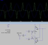
I have designed this class-C amplifier which works on both input sinewave peaks.
As expected, this waveform is produced only when the input sine peaks are at about 0.7v.

Is there any way I can make this (or another class-C) amplifier working in the uV levels?
 

Attachments

  • tmp.JPG
    tmp.JPG
    70.2 KB · Views: 24
  • tmp.zip
    811 bytes · Views: 13

BigBoss

Advanced Member level 6
Joined
Nov 17, 2001
Messages
5,524
Helped
1,574
Reputation
3,150
Reaction score
1,467
Trophy points
1,393
Location
Türkiye
Activity points
33,316
-There is no way to build a Class-C Power Amplifier working at uV level.(Transistors won't work at that level)
-Why you use Class-C Amplifier ?? This generally is used for High Efficiency Power Amplifiers. Do you really need this ?
 

    neazoi

    Points: 2
    Helpful Answer Positive Rating

neazoi

Advanced Member level 6
Joined
Jan 5, 2008
Messages
4,054
Helped
13
Reputation
26
Reaction score
14
Trophy points
1,318
Location
Greece
Activity points
36,377
-There is no way to build a Class-C Power Amplifier working at uV level.(Transistors won't work at that level)
-Why you use Class-C Amplifier ?? This generally is used for High Efficiency Power Amplifiers. Do you really need this ?
I thought it could be used as a simple "dead zone" amplifier on HF (2-30MHz), where only the higher level signals could be amplified (the ones that cause the transistor to conduct). I just wanted to see if this threshold level could be reduced.

Danadakk in this thread https://www.edaboard.com/threads/rf-detector-with-my-comparator.396013/ post #7 made the transistors to start conducting from lower levels (although not uV). I was hoping that something similar could be done in a class-C amplifier, so that the level of the peaks the amplifier amplifies is reduced to much lower levels.

Obviously a class-A preamplifier before a class-C can be used to amplify signals to the class-C threshold level, but this raises IMD (signals nonlinear mixing) problems and this is exactly what I want to avoid.

One thing that I want to know about class-C amps, is, how will a class-C circuit behave under the presence of a strong amplitude sine in one frequency (that is able to trigger the amplifier) and a very low amplitude signal on another frequency? At the time that the amplifier conducts (due to the presence of the high level signal), it would amplify both signals, the low and the high ones, isn't that true?
 
Last edited:

G4BCH

Advanced Member level 1
Joined
May 10, 2006
Messages
443
Helped
133
Reputation
268
Reaction score
124
Trophy points
1,323
Activity points
5,515
One thing that I want to know about class-C amps, is, how will a class-C circuit behave under the presence of a strong amplitude sine in one frequency (that is able to trigger the amplifier) and a very low amplitude signal on another frequency? At the time that the amplifier conducts (due to the presence of the high level signal), it would amplify both signals, the low and the high ones, isn't that true?
What you describe here is an active mixer. The low level signal will be 100% modulated by the high level signal. The output will be both signals together with the sum and difference frequencies. There will also be harmonic sum and differences present.
Putting non linear devices in the signal path of a receiver is a bad idea, Receiver designers go to great length to ensure that the signal path is as free from distortion as possible.
 

BigBoss

Advanced Member level 6
Joined
Nov 17, 2001
Messages
5,524
Helped
1,574
Reputation
3,150
Reaction score
1,467
Trophy points
1,393
Location
Türkiye
Activity points
33,316
As far as I understand, you intend to amplify a signal that exceeds a certain power level, right ??
If it's so, two questions should be answered.
-The system has to get the information about signal strength
-And the same system will amplify this signal

I believe a RSSI+Amplifier with Inhibit Feature can work.
RSSI will detect the signal level and the rest of the circuit amplifies the signal with this inhibit feature.

C-Class amplifier can work but it creates so many harmonics and driving level is pretty high.
 

    neazoi

    Points: 2
    Helpful Answer Positive Rating

neazoi

Advanced Member level 6
Joined
Jan 5, 2008
Messages
4,054
Helped
13
Reputation
26
Reaction score
14
Trophy points
1,318
Location
Greece
Activity points
36,377
As far as I understand, you intend to amplify a signal that exceeds a certain power level, right ??
If it's so, two questions should be answered.
-The system has to get the information about signal strength
-And the same system will amplify this signal

I believe a RSSI+Amplifier with Inhibit Feature can work.
RSSI will detect the signal level and the rest of the circuit amplifies the signal with this inhibit feature.

C-Class amplifier can work but it creates so many harmonics and driving level is pretty high.

You are in the right path. These are the problems I encountered with a class-C amplifier indeed.
It would be really helpful if you can give me a circuit example, anything you can find on the web etc, as a starting point to get me started with it on the right path.
 

FvM

Super Moderator
Staff member
Advanced Member level 7
Joined
Jan 22, 2008
Messages
51,003
Helped
14,633
Reputation
29,542
Reaction score
13,742
Trophy points
1,393
Location
Bochum, Germany
Activity points
291,794
Class-C doesn't amplify µV signals. If you bias it respectively, it becomes class-A (for µV signals) or class-AB (for gigher level).

It's still umclear what you want to achieve.
 

    neazoi

    Points: 2
    Helpful Answer Positive Rating

BigBoss

Advanced Member level 6
Joined
Nov 17, 2001
Messages
5,524
Helped
1,574
Reputation
3,150
Reaction score
1,467
Trophy points
1,393
Location
Türkiye
Activity points
33,316
You are in the right path. These are the problems I encountered with a class-C amplifier indeed.
It would be really helpful if you can give me a circuit example, anything you can find on the web etc, as a starting point to get me started with it on the right path.
OK, look at this Power Detector here.
It has very wide dynamic range and it's pretty accurate. There are lot of information how to implement in datasheet.
All you need si to use a Comparator at DC output of this detector and when a well defined level is exceeded, the comparator will inhibit the amplifier.
TRF37A73 has a Power Down input and this can be connected to comparator output.
 

    neazoi

    Points: 2
    Helpful Answer Positive Rating

neazoi

Advanced Member level 6
Joined
Jan 5, 2008
Messages
4,054
Helped
13
Reputation
26
Reaction score
14
Trophy points
1,318
Location
Greece
Activity points
36,377
OK, look at this Power Detector here.
It has very wide dynamic range and it's pretty accurate. There are lot of information how to implement in datasheet.
All you need si to use a Comparator at DC output of this detector and when a well defined level is exceeded, the comparator will inhibit the amplifier.
TRF37A73 has a Power Down input and this can be connected to comparator output.
Hm...
What if strong signals on other frequencies, are presented in the input of the RSSI? This will five a false triggering on the actual signal we want to level-amplify.

You made me think now, how about a BPF, followed with a single transistor preamplifier, which drives an envelope detector. The envelope detector output drives a comparator and it's output allows or shunts (through a transistor) the signal output?
As long as the input signal level is high enough (again a filter is needed), the output will not be shunted to ground.
 

BigBoss

Advanced Member level 6
Joined
Nov 17, 2001
Messages
5,524
Helped
1,574
Reputation
3,150
Reaction score
1,467
Trophy points
1,393
Location
Türkiye
Activity points
33,316
Hm...
What if strong signals on other frequencies, are presented in the input of the RSSI? This will five a false triggering on the actual signal we want to level-amplify.

You made me think now, how about a BPF, followed with a single transistor preamplifier, which drives an envelope detector. The envelope detector output drives a comparator and it's output allows or shunts (through a transistor) the signal output?
As long as the input signal level is high enough (again a filter is needed), the output will not be shunted to ground.
RF Power Detector can already not distinguish the incoming frequencies where they are coming from. It measures Average Power Level of all incoming signal(s). In order to discriminate a particular signal, you have to use either a sharp BPF or Mixer+Oscillator and BPF ( or Crystal, SAW or any other very selective filter) to measure IF signal.
By this way, you will able to measure and control your particular signal.
 

    neazoi

    Points: 2
    Helpful Answer Positive Rating

LaTeX Commands Quick-Menu:

Part and Inventory Search

Welcome to EDABoard.com

Sponsor

Top