Continue to Site

Welcome to EDAboard.com

Welcome to our site! EDAboard.com is an international Electronics Discussion Forum focused on EDA software, circuits, schematics, books, theory, papers, asic, pld, 8051, DSP, Network, RF, Analog Design, PCB, Service Manuals... and a whole lot more! To participate you need to register. Registration is free. Click here to register now.

Circuit to shift negative voltage zero

Status
Not open for further replies.

PYGuj

Junior Member level 1
Joined
Jul 22, 2014
Messages
18
Helped
0
Reputation
0
Reaction score
0
Trophy points
1
Activity points
132
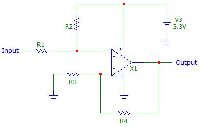
Hello. I am using a circuit whereby i am having both negative and positive values as output. I need to shift the negative voltage above zero so that i can input it directly to a microcontroller which can accept 0 to 3.3V at the ADC. how can i do this with the help of op amps? Thanks!!
 

You have to specify the range of variation of your signal. Do you know the output impedance of the circuit generating the signal ? It could be a simple resistor network can do the job.
 

Thanks for the reply. Actually i am using the output of a pre-built strain gauge amplifier so it is quite difficult to be sure about the output impedance and also the signal from the the amplifier keeps fluctuating too much for the application i am using it. I have tried logging the data from the amplifier which gives peak values upto 1V in the positive direction but the negative values are just assigned a value of zero by the microcontroller. to be on safe side i will want to shift -1.5V since i really do not know exactly what range the negative values can reach (but i assume not lower than -1.5V).
 

Hi,

Say it mathematically. "Shift up" means to add voltage.
So simply add 1.5V.

To ease mathematics with the digital values you should add half of adc input range.
On the digital side you may subtract half of adc range.

Maybe you have to decrease gain to avoid overflow.


Klaus
 

You can use this op-amp based circuit:


The first two resistors will rise the voltage making it positive. Applying KVL and KCL you can easily see that if Vr is the voltage going to the non-inverting pin og the op-amp and Vi is the input voltage:

Vr=Vi+R1*(3.3-Vi)/(R1+R2)

then shifting -1.5V to zero means:

0=-1.5+R1*(3.3+1.5)/(R1+R2) from which

R1/(R1+R2)=1.5/4.8=0.3125 or 1+R2/R1=3.2 that is R2=2.2*R1

In this case when the input voltage reaches +1V we will have:

Vr=1+0.3125*(3.3-1)=1.719 V

In order to cover the whole dynamic range of the ADC (0-3.3V) we have to amplify by a factor:

Av=3.3/1.719=1.92

Using the op-amp in a non-inverting configuration as depicted in the image, the gain is

Av=1+R4/R3, then R4=R3*0.92

You can choose, now R1 much greater than the output impedance of you circuit; R1=10K should be OK, then R2=22K. Now you can choose arbitrary R3=18K then R4≈15K.

The actual tranfert function will be Vout=[Vi+R1*(3.3-Vi)/(R1+R2)]*(1+R4/R3) using the value just calculated:

Vout=1.89+1.2581*Vi

Don't forget to choose a single supply, rail to rail amplifier.
 
Last edited:
  • Like
Reactions: PYGuj

    PYGuj

    Points: 2
    Helpful Answer Positive Rating
Thanks very much for the detailed explanation. this surely helps me a lot. will try implementing it today in lab!
 

Why at all is the output fluctuating by as much as 1V? Another question would be... will the readings be reliable even after adding an offset? Such spurious fluctuations are indicating perhaps something worse!
 

I have tried to change some resistor values but still the same thing. I have not yet seen the problem!
 

Hi,

If you show the strain gauge amplifier circuit maybe we can assist you there.


Klaus
 

Hello! Herewith attached the picture of the strain gauge amplifier circuit. Thanks!

20140725_132401.jpg
 

Select a red LED with a characteristic voltage-drop of 1.5v.
Connect a 10k and red LED in series with the 10k to the 3v3 line.
Connect the cathode of the red LED to the output of your strain gauge.
Connect a DMM to the join of the 10k and anode of red LED. It will read 0v to 3v
 

Hi,

regarding the circuit.
I just had a view to the PCB and the informations given by RS.

Do youknow how it work? It seems it is an DC supplied bridge with a high gain amlifier.
If so, then i doubt it is a good solution. There are at least two BJTs in the low voltage signal path. Without temperature compensation.
The BJTs drift with 2mV/K and maybe the amplifier has a gain of 50 then it gives a temperature dependency of 100mV/K.
For sure some of this my cancel itself, but if 90% is canceled out there are still 10mV/K.

If you want to test the quality and drift then use two 500 Ohms resitor and a 1Ohm resistor. Solder all three in sereies with the 1 Ohms in dhe middle.

Use this as known and fixed sensor signal. It has an output of 1mV/V if you connect the supply to the ends (ech 500 Ohms resistor) and the sensor out (= amplifier in) to the 1 Ohms connections.

If you use 1% resistors then the circuit is pretty reliable.

Now show if the output of the amplifier still drifts.
Try to carefully wam the PCB to see what happens to the output voltage.
With a scope you can get an impression about noise.

Klaus
 

Thank you very much! i will try to do that in lab on Monday and come back with some answers to your questions. as for the resistors i have used all 1% as recommended.
 

hi. a quick feedback about what i did. before implementing the above i tried the circuit with a full wheatstone bridge. i am using the output of the amplifier as a control parameter to actuate a servo motor via some programming with mbed controller. i supplied the amplifier with +12V and -12V and a separate 0-5V supply for the servo. however, transistor T2 heats up very much and burns resistor R8. what can be the problem now?
 

Hi,

i don´t have the schematic by hand...
Did you connect all 0V / Gnd lines of each supply together?

Klaus
 

hello. yes i connected all together and even tried connecting separately but same result.
 

Hi,

i don´t trust that circuit much...

R8 sould limit current to about 60mA.
If it limits to 60 mA then power loss is about 36 mW. No need to get hot...


Klaus
 

Status
Not open for further replies.

Part and Inventory Search

Welcome to EDABoard.com

Sponsor

Back
Top