Continue to Site

Welcome to EDAboard.com

Welcome to our site! EDAboard.com is an international Electronics Discussion Forum focused on EDA software, circuits, schematics, books, theory, papers, asic, pld, 8051, DSP, Network, RF, Analog Design, PCB, Service Manuals... and a whole lot more! To participate you need to register. Registration is free. Click here to register now.

Circuit to discharge a capacitor once it crosses a particular voltage

Status
Not open for further replies.

amsdesign

Member level 3
Member level 3
Joined
Aug 26, 2015
Messages
67
Helped
0
Reputation
0
Reaction score
0
Trophy points
6
Activity points
550
I want to build a circuit that keeps monitoring a capacitor's voltage and once the voltage crosses a particular threshold the capacitor should discharge and come back to it's threshold.

This is what I came up with, the moment the capacitor crosses the threshold, the resistor will turn on the NMOS and the cap is discharged to ground.
Any reasons why this circuit won't work/better ideas?

Thank you,
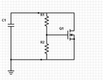
self-turn off.JPG
 

The circuit implements a V/I characteristic according to the transistor Id = f(Vgs) curve and the voltage divider ratio. You should determine if it's steep enough. An amplifier or comparator can give you a steeper characteristic, depending on what you need.

Presently, there's no source charging the capacitor, so it stays at zero voltage.


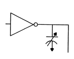
@FvM : The capacitor is connected to a variable delay ring oscillator, like shown below. So once the delay crosses a particular threshold the circuit should react and bring it down to its old value.

variable.png

Also, can you elaborate on your point regarding the curve not being steep enough, I did not understand that part.
 

In simple words, it's a clamping device. Required properties (dynamic impedance, speed) are up to your specification.
 

In simple words, it's a clamping device. Required properties (dynamic impedance, speed) are up to your specification.

In this case I don't really need any strict property to be satisfied do I? The circuit should merely perform the function of draining the cap.
 

Hi,

Your circuit won't discharge the capacitor to near zero volts. It just limits it's voltage at a dedicated level.
This is not the function you describe.

It seems you more want the function of a diac.

You should specify your function.
What peak voltage level?
How fast should it discharge?
To what voltage value should it discharge?

Klaus

@Klaus, well I do not want the cap to discharge to zero volts. I'm talking in the range of micro-volts here and almost an instant discharge. Will a diac help me out here?
 

If I suggest a diode together with a reference voltage source, is there any requirement ignored?

Surely you can't expect microvolt accuracy, not even with an active circuit.
 

You need a negative resistance device to perform this task. Old school was to use a Unijunction or now a DIAC, still used today with Triac triggering.

Depending on frequency and size of capacitance, this means you need hysteresis to detect and then force discharge well below threshold then float. THis is done with positive feedback ratio or Schmitt trigger to FET.

But source/input capacitance ratio must be large and switch recovery time must be low for this to be reliable.

- - - Updated - - -

I want to build a circuit that keeps monitoring a capacitor's voltage and once the voltage crosses a particular threshold the capacitor should discharge and come back to it's threshold.

This is what I came up with, the moment the capacitor crosses the threshold, the resistor will turn on the NMOS and the cap is discharged to ground.
Any reasons why this circuit won't work/better ideas?

Thank you,
View attachment 120744

All you have designed here is a programmable zener with a R ratio divider threshold for Vgs also dependent on Source impedance ratio.
 

Check out Programmable Unijunction Transistors (PUTs) type 2N6028 and 2N6027.

But no, you won't discharge the capacitor to microvolt levels.
 

Status
Not open for further replies.

Part and Inventory Search

Welcome to EDABoard.com

Sponsor

Back
Top