Continue to Site

Welcome to EDAboard.com

Welcome to our site! EDAboard.com is an international Electronics Discussion Forum focused on EDA software, circuits, schematics, books, theory, papers, asic, pld, 8051, DSP, Network, RF, Analog Design, PCB, Service Manuals... and a whole lot more! To participate you need to register. Registration is free. Click here to register now.

Circuit to detect clock with a little higher frequency

Status
Not open for further replies.

sun_ray

Advanced Member level 3
Joined
Oct 3, 2011
Messages
772
Helped
5
Reputation
10
Reaction score
5
Trophy points
1,298
Visit site
Activity points
6,828
We have two different clock generators. The frequency of one clock from one generator is very slightly higher than the clock from the other generator. Can you please provide a design that will be able to state which clock has a higher frequency?

Regards
 

There are probably a million ways to do this. You don't state the frequencies involved, or how close they are.

One way to do it: Enable a gate for a relatively long period of time, and have both clocks increment counters. At the end of the gate period, see which counter has the larger number (that's the faster clock).
 

This method will be OK when simulation. But If it will be realized to a curcuit, maybe one issues will happen. Which clock domain the gate signal is drived in? If in A clock domain, it will be sync two beats to control B clock domain, and then the counter accuracy will be influenced.
 

This would make a good competition ...how many solutions to the same problem ;-)
 

There are probably a million ways to do this. You don't state the frequencies involved, or how close they are.

Let us take that the frequencies are very close.

One way to do it: Enable a gate for a relatively long period of time, and have both clocks increment counters. At the end of the gate period, see which counter has the larger number (that's the faster clock).

Which enable are you stating here? Which gate are you stating here? Can you please draw the circuit as the schematic of the circuit is not very clear.

Thanks for the reply.

Regards
 

Let us take that the frequencies are very close.


Which enable are you stating here? Which gate are you stating here? Can you please draw the circuit as the schematic of the circuit is not very clear.

Thanks for the reply.

Regards

How close is "very close"? This is engineering, not semantics.
 

For example if on clock is with frequency 200 MHz, the other clock is with frequency 200.01 MHz.

Regards

Ok, now we're getting somewhere. So (and this is a brute-force, not-well-thought-out solution) do this: Have the 200 MHz clock, call it clock A, drive a 24-bit counter which generates an output that is high for 8,388,608 clocks (.04194304 sec). Use this output to enable a second counter which is driven by the other clock (clock B). Forgetting about synchronization for now, the clock B counter will see 8,389,027 counts in the same time the first counter saw 8,388,608 counts.

- - - Updated - - -

Here's another ill-conceived idea: use a mixer and filter; the output of the mixer will be the sum and difference of the signals, the filter will eliminate the sum term.
 

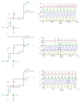
I have used this in one of my designs for a similar purpose. It may be adapted for this application if the clocks can be divided down or suitable high-frequency gates are available.
For any slight difference in the clock frequencies, you will get two outputs; one at the clock rate and one at twice the clock rate.
If the two clocks are the same frequency and duty cycle, then both outputs remain low.
If the two clocks are the same frequency but different duty cycles, the outputs will be pulses at the clock rate.
 

Attachments

  • freq_det.gif
    freq_det.gif
    47.9 KB · Views: 158

Status
Not open for further replies.

Part and Inventory Search

Welcome to EDABoard.com

Sponsor

Back
Top