Continue to Site

Welcome to EDAboard.com

Welcome to our site! EDAboard.com is an international Electronics Discussion Forum focused on EDA software, circuits, schematics, books, theory, papers, asic, pld, 8051, DSP, Network, RF, Analog Design, PCB, Service Manuals... and a whole lot more! To participate you need to register. Registration is free. Click here to register now.

circuit to check the ferrite core transformer

Status
Not open for further replies.

sankposh

Junior Member level 3
Joined
May 8, 2010
Messages
25
Helped
0
Reputation
0
Reaction score
0
Trophy points
1,281
Location
India
Activity points
1,443
I have brought ferrite core transformer for my project.
I want to test it whether its properly working or not.
Before applying to my circuit.
Can I test with some circuit
Here is the transformer specification.

Ferrite core transformer
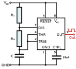
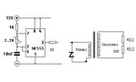
Frequency :- 10 Khz
Primary Voltage :- 12 Vdc
Primary current :- 120 ma
Secondary Voltage :-1000 V
Secondary Current :- 1.44 ma

How can I test the following transformer whether iam getting
proper output or not
Suggest some circuit to check the ferrite core transformer
 

Dear sankposh
You can check the transformer inductance,turnsratio and leakage inductance,If all the reading are observing as per your design, then you will get the proper output.
Regards
lib
 

From the top of my head, 555-timer can drive loads (sink & source) up to 200mA, so if you build a test generator based on the 555-timer (astable mode) you should be able to test your transformer ..

555 timer IC - Wikipedia, the free encyclopedia

IanP
:wink:
 

Attachments

  • 555_Astable_Diagram_svg.png
    555_Astable_Diagram_svg.png
    4.4 KB · Views: 155

From the top of my head, 555-timer can drive loads (sink & source) up to 200mA, so if you build a test generator based on the 555-timer (astable mode) you should be able to test your transformer ..

555 timer IC - Wikipedia, the free encyclopedia

IanP
:wink:

can you suggest me circuit so that i can test
with all transformer primary secondary connection
 

See attached drawing ..
For tests you should use a regulated power supply with adjustable current limit ..

IanP
:wink:
 

Attachments

  • 555-transformer-load2.jpg
    555-transformer-load2.jpg
    19.5 KB · Views: 179

Your transformer is high voltage transformer (1 kV output), so with large number of turns in the secondary and large parasitic capacitance. Contrary to low voltage transformer, the transformer is like a resonant LC circuit and it works fine only at is resonant frequency!
 
  • Like
Reactions: Libin

    Libin

    Points: 2
    Helpful Answer Positive Rating
See attached drawing ..
For tests you should use a regulated power supply with adjustable current limit ..

IanP
:wink:
but tell me the exact way to do the circuit checking
do i need to generate 12v square wave pulse and need to apply it
also the secondary of transformer u have used a divider of 1 Mohm
suggest me solution for it
as the Ic is getting hot
 
Last edited:

As i have check the constructed circuit i find out that 555 get heated
what could be the reason for it.
is their another circuit using mosfet irf820 etc from which i could test the circuit
 
Last edited:

See attached drawing ..
For tests you should use a regulated power supply with adjustable current limit ..

IanP
:wink:

how i could test the circuit as i have find out that 555 gets heated and iam not getting output from transformer
is their another circuit using mosfet i culd test
 

You may boost the output from the 555-tomer by placing a complementary emitter follower between the 555 and the transformer ..
NPN + PNP, bases tied together connected to 555 via 100R resistor ..
Emitters tied together connected to transformer, NPN collector to +12V, PNP collector to 0V .


:wink:
 

The originally suggested circuit should be supplemented by a coupling capacitor, otherwise you're possibly saturating the core.

The below transformer specification is apparently based on ideal transformer properties (infinity main inductance, zero leak inductance, zero windings resistance, zero capacitance). In so far it's clear, that no real transformer can have this data. It would be interesting to have an idea of the real data to set up the test circuit.
 

You have to put a coupling capacitor like suggested by "FvM".
But read carefully my first post. If the 555's frequency is lower than the transformer resonant frequency, the 555 see a large capacitor, not an ideal transformer!
Charge and discharge of this capacitor heat the 555, and there little or no output voltage!
I worked during 30 years on High Voltage Power Supplies...
 
  • Like
Reactions: Libin

    Libin

    Points: 2
    Helpful Answer Positive Rating
HELLO,
My name is Yadnesh Samant. Currently i m making BE project on Isolated SMPS e.

I need a ferrite core transformer with following specifications:-

Shape=>E-I core (ferrite - core transformer)
Vin= 7.5 volts to 8 volts
Vout1= 7.5 volts
Vout2=5 volts
frequency=52Khz
Nprimary= 17 turns
Nsecondary=17 turns
Nauxillary-secondary=12 turns ( ek primary and 2 secondary)

CAN U JST HELP ME HOW DID U SELECTED THE NO. OF BOBBINS AND HOW TO CALCULATE THE CORE AREA...
IT WILL BE OF G8 HELP.
THNKS IN ADVANCE
 

Status
Not open for further replies.

Similar threads

Part and Inventory Search

Welcome to EDABoard.com

Sponsor

Back
Top