Continue to Site

Welcome to EDAboard.com

Welcome to our site! EDAboard.com is an international Electronics Discussion Forum focused on EDA software, circuits, schematics, books, theory, papers, asic, pld, 8051, DSP, Network, RF, Analog Design, PCB, Service Manuals... and a whole lot more! To participate you need to register. Registration is free. Click here to register now.

[SOLVED] Circuit for testing a x-tal

Status
Not open for further replies.

hafrse

Full Member level 3
Joined
Aug 6, 2007
Messages
169
Helped
1
Reputation
2
Reaction score
3
Trophy points
1,298
Activity points
2,413
Hello,

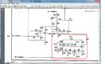
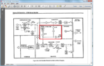
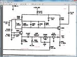
I am looking for a simple circuit diagram for testing a 29Mhz crystal which is supspected to be faulty, it is inside an instrument and the 29Mhz signal stopped working .
Many thanks in advance ! George
 

Since they have almost infinate resistance and very low capacitance it's very difficult to test them without specialist equipment.

If you have a signal generator you can feed a small voltage (say 100mV) into one pin and monitor across a load at the other. It should show a conduction of signal only at the resonant frequency. Alternatively, the method used by most crystal testers is to plug it into an oscillator circuit and see what happens. If you have anther crystal near to 29MHz you could try substitution just to see if the rest of the circuit is working but by it's nature a different frequency will probably not work properly in your device.

Brian.
 
  • Like
Reactions: hafrse

    hafrse

    Points: 2
    Helpful Answer Positive Rating
Hi , tested as described, x-tal is working.

Many thanks!

George
 

Hi Again,

No luck in getting the oscillator circuit to work, I did almost every thing I can, changed the NPN transistor, varicap, checked all resistors, caps.
However, I have the schemtics for the osccilator itself but only from a newer version serial numbers (it has been completley redisinged and now it has two NPN transistors instead) and I am trying to build the oscillator in an experemental board. Uploaded the schemtics.

oscillator is in the red area.

One question I have, the caps has no unit units , is the unit nF ? so .01 is 10pf?

Inputs are: -5.2V Bias and LOTUNE voltage for varying the frequency around its main x-tal frequency
Power is +10v

Output at C112

Thnaks
 

Attachments

  • 29mhz_lo.png
    29mhz_lo.png
    170 KB · Views: 97
Last edited:

The capacitor values marked .01 are .01uF (10nF) and should be disc ceramic types. All the others are in pF, sorry, I can't read their references from the PDF.

It could still be the crystal of course, they occasionally go 'lazy' but it's rare. If you are building a clone, take great care to keep the wiring length as short as possible and try altering the tuning voltage, it's possible the circuit will not oscillate if the voltage is too far out of it's expected range.

Brian.
 
  • Like
Reactions: hafrse

    hafrse

    Points: 2
    Helpful Answer Positive Rating
Many Thanks for your help, regarding the caps in the schematic (its is a tek SA) , is this a kind of standard where decimals like .01 are always .01uf and thoes without like 1 are 1pf ? alos wanted to know what you meant by "I can't read their references from the PDF".

Some more information:
Regarding the tuning voltage it comes from a 11bit dac and on startup it has +3.72V (mesaured by me).
The 29Mhz oscillator is used to mix a 25mhz IF signal comming from other higer frequnecy mixers to produce a 4Mhz signal
also, the 29Mhz signal is counted (29 CNT on the block diagram) by the CPU which also controls the 11bit dac to tune the oscillator.

Attached is a block diagram.

George
 

Attachments

  • block_29.png
    block_29.png
    189.5 KB · Views: 78
Last edited:

Many Thanks for your help, regarding the caps in the schematic (its is a tek SA) , is this a kind of standard where decimals like .01 are always .01uf and thoes without like 1 are 1pf ? alos wanted to know what you meant by "I can't read their references from the PDF".

It isn't a standard, Tek assume anyone capable of reading the schematic would be able to guess. I think the full component list is at the back of their manuals if in doubt.

What I meant by the references was the pdf you posted wasn't clear enough to read the component reference numbers 'Cxxx' and so on.

Why I queries the tuning voltage was that if it was below (more negative) than -5.2V it would certainly stop it working because the tuning diode would load the circuit too much. A positive voltage should be OK as it keeps the diode reverse biased.

Brian.
 
  • Like
Reactions: hafrse

    hafrse

    Points: 2
    Helpful Answer Positive Rating
Thanks again, will buy the componnets and will solder it on an experimental Eurocard with very short connections, will also update this thread in few days!

Best regards,
George
 

Update:

I bought a new x-tal and still did not work in the tek pcb.

I rebuilt the circuit on a veroboard with very short leeads and connections but still no luck. Do I realy need the offset voltage of -5.2v and a tune voltage to run the oscillator or it will run anyeay ? however, if I touch with my finger the back side of the veroboard I can read a 29Mhz signal on my scope, but not stable. I also injected a -5.2 v but nothing happens there.
Thanks for any help on how to troubleshoot the circuit.

George
 

The -5.2V has to be there I'm afraid. You also have to apply some voltage at the LOTUNE line although for testing this can be anythng from about 0V to 5V, what is important is it isn't left floating.

The reason is that the varicap diode (CR28?) has to be reverse biased. If it starts to forward conduct it will change from looking like a capacitor into looking like a low value resistor and it will detune the crystal. I'm guessing the DAC produces between 0V and +5V so the voltage across the diode will be between 5.2V and 10.2V. The higher the voltage, the lower its capacitance will be, that's how the frequency is pulled by the ADC output.
The reason I queried the tuning voltage in post #7 is that if the voltage is outside it's design range, the capacitance of the varicap may shift enough to stop the oscillator running.

Brian.
 
  • Like
Reactions: hafrse

    hafrse

    Points: 2
    Helpful Answer Positive Rating

Without the full manual I can't see if the DAC is part of a PLL system, in which case it would to some degree be self correcting, but if I assume it isn't and simply produces a 'fine tuning' voltage, what you measured seems reasonable. The choice of transistors seems OK, possibly the varicap has higher capacitance than the original, based on the schematic showing a fixed 1pF capacitor across it but again that shouldn't stop it running. Can you measure the DC voltages around the transistors and actually at the varicap and let us know what you find please. Another test you might be able to try is to sweep a nearby radio receiver around say 28 - 30MHz and check if it is oscillating but being stopped when your oscilloscope/frequency counter loading the output.

Brian.
 
  • Like
Reactions: hafrse

    hafrse

    Points: 2
    Helpful Answer Positive Rating
Hello,

You are right, it is somehow oscillating, but not no output c112 : If I measure (oscilloscope set to AC mode) the Base on the PNP transistor at the right, then I can see a frequency stable at about 780mV 29.00Mhz signal !!! but it will dissapear or changes amplitude if I started to touch the ground plane or other conponents, it also dissapears sometime.
Also, oscillation is avialble at c112 after I put my finger on the components in some way.

Have I missed something here or done something wrong in my clone circuit? do I need to build it in a different way with gound points every where?

Conditions:
DC Power in is +10.28V from a power source.
Bias -5V from a power source
Tune voltage is set to 0V by a 10k resistor to ground.
The circuit is stand alone and not connected to the analyzer, I just wanted to see if it works before I install it.

MEasured values:
right transistor: C=+9.25 E=+6.95 B=+7.63
Left Transistor: C=+7.63 E=+4.42 B=+5.14
Voltage across the varicap is -5v


- - - Updated - - -


Regarding your comment on the circuit if is a part of a some kind of loop, as described in the manual is that the 29 signal is counted by the processor and feedback is sent to the tune voltage of the varicap, as you can see from the block diagram, the counted signal ois the 29 CNT.

George

- - - Updated - - -

Updated with more info from the manual
 

Attachments

  • text.png
    text.png
    331.1 KB · Views: 83
  • 29mhz_lo.png
    29mhz_lo.png
    170 KB · Views: 82
  • dac.png
    dac.png
    201.3 KB · Views: 80
  • block_29.png
    block_29.png
    237.5 KB · Views: 79
Last edited:

All is not lost! I may be that your oscilloscope probe is making it start oscillating or it could be that the load after C112 is needed for it to oscillate. The fact that it did something at 29MHz is encouraging. When in the rest of the unit, there is quite a low impedance (my guess is around 100 Ohms) loading the output end of C112 and this may be essential for it to work properly. You can test this by addng a load resistor to ground after C112 and connecting your scope across it. Iw ould only expect a few 10s of mV signal so don't expect a large waveform.

Brian.
 

Thanks, will do that but what value should I choose? will also try witha HF radio at 29Mhz to hear if there is a tune when the oscilloscope probe is not there
 

Hello,

Did that with a 100 Ohms. did not help. However, as you said, it is the probe that start the oscillation when attached to the base of the right transistor, if I put channek B probe on that too, it will stop... also, some times it does not start, when it stops I need to touch the card and then it starts again.
May be I need to rebuild it on a coppar laminated card where I have a good ground there , it is worth a try.


By the way, I tried to drow the schematic of the oscillator from the version I have in my instument (as I mentioned in my first posts, I have a different version), I have a capacitance meter which is good from 1 nf and is not realable. Will post the schemtics later here. It only has one transistor, and Tektronix redesignd it as described in the pictures I posted before. May be I can fix that to work ?
I will try to borrow a capacitance meter which is good from .01pf desolder alll the caps and check them if there is an open cap, I swaped the varicap and the transistor there but no luck, checked all the resistors, all seems to be ok. What I suspect is one of the caps is open.
Will post the picture soon.
George

George
 

I am trying to analyze the circuit, but some of the values are not clear. Could you edit the drawing in MS paint or something and give the values of the components?
 

Thanks for your help, attached is a better picture.
caps in 1 and up are in pF (33 is 33pf, caps less than 1 are in uF (.01 is .01uf)
Goerge
 

Attachments

  • lo.jpg
    lo.jpg
    254.8 KB · Views: 80

Lift the one side of the resistor I marked and see if it gives a better output level. They use that to lower the Q of the 10uH choke that couples the DC bias to the 2nd transistor's base. Depending on what the Q of your 560nH coil is, that value may lower the Q of the tank too much for oscillations to start and be reliable.

Make sure that it is not a printing mistake on the diagram. The value is unusually low and would place serious damping on the 560nH/33pF tank. Verify against the parts list in the manual.

********************************************
Ok, I have run a simulation on the circuit, and the 274Ω resistor's dual purpose seems to dampen any overtone oscillations from the crystal as well as lowering the Q of the 10uH choke to prevent any resonances that might occur. Thus the output is not very high, but it does not need to be as it is coupled into another transistor stage. Increasing the the 274Ω above 470Ω makes it go spurious. I have used general purpose transistors in the simulation which can easily handle 29MHz.
 

Attachments

  • 29_osc.gif
    29_osc.gif
    33.4 KB · Views: 72
  • 29M_osc.gif
    29M_osc.gif
    110.5 KB · Views: 77
Last edited:

Many thanks for your time in the simulation, I lifted the resistor, no luck there, it will only oscillate at the base of the right transistor only when I put the osc. probe at that place, it seems that the probe kicks the oscillation on.... I think there is something wrong in the current circuit, I will rebuild the circuit hopfully today and only use none smd components . I do not have the complete manual and no part list is available. What simulation program are you using ?
Regards
George
 

Status
Not open for further replies.

Similar threads

Part and Inventory Search

Welcome to EDABoard.com

Sponsor

Back
Top