Continue to Site

Welcome to EDAboard.com

Welcome to our site! EDAboard.com is an international Electronics Discussion Forum focused on EDA software, circuits, schematics, books, theory, papers, asic, pld, 8051, DSP, Network, RF, Analog Design, PCB, Service Manuals... and a whole lot more! To participate you need to register. Registration is free. Click here to register now.

[General] Circuit for pulse generation

Status
Not open for further replies.

geoengineering

Newbie level 5
Joined
Oct 3, 2013
Messages
9
Helped
0
Reputation
0
Reaction score
0
Trophy points
1
Activity points
64
Hi
I have pressing need for the following pulse:
The Square Wave specifications are as follows:
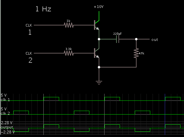
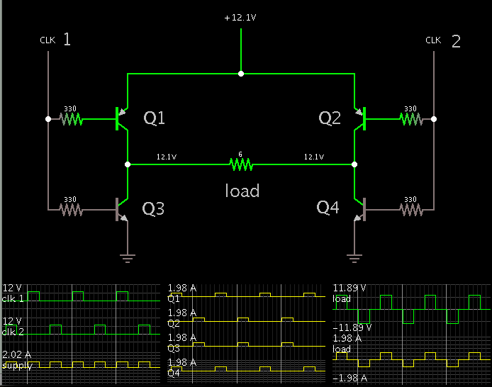
The pulse consists of: ON(Positive voltage)- OFF- ON(Negative voltage)- OFF .........
T(ON)= T(OFF)
X1= 0.25 S – 8 S
X2= Number of cycles = 2- 4- 6- 8- 10
X3= output voltage
In this circuit output voltage and output current should be variable and X1, X2 and start trigger should be obtained with USB port (LABVIEW software) or keyboard or other
Please help me with schematic; PCB; program; about this circuit;
Pulse is shown in the following image.
I wish you all the best
Thanks;
SHEMATIC.jpg
 

if you want negative voltage then should be having center tap transformer then what voltage you want on peak to peak.
 

First,Thank you for your attention
output voltage can be 0 - 15v and current is 0- 2 A or Any amount that you can design. Output waveform should be Similar to the proposed.
X1 and X2 and X3 and start trigger can be Regulated with use keyboard or USB interface (by labview software).
If the project is large, Please send for me the circuit design with generate the square wave with this waveform without attention to other cases,
Thank you very much
 

which controller you are using and check if there is PWM is available or not?
because as you have given variable then i think on time should be changed so PWM will help you.
 

HI
First,Thank you for your attention
AVR microcobtroler using in this project and no problem to use each type of it.
please help me for design and generation this waveform
 

This illustrates a simple way to get positive and negative AC square waves, with no need for a negative supply.

The output amplitude is much less than the supply V.


There are other configurations you can use if your supply is bipolar and you can provide bipolar clock signals.
 

at first, Thanks very much for your guidance and attention
I have a few questions about this circuit:
1- How can calculate the value of the output voltage?
2- I need a voltage of about 12 volts and current of about 2000mA That should be changed: [0-12] and [0-2000]
3- Please Explain more, about generation CLK1 and CLK2?
4- What software have you used for this circuit?
I wish you all the best
 

1- How can calculate the value of the output voltage?

With the half-bridge (my post #6 schematic), the output amplitude can only attain 1/2 of the supply V.

My schematic has a 10V supply, hence the output can attain +- 5V max. This is after I increased the driving voltage at the transistor bases to 10V each. (Previously it was 5V each, causing a meager +- 2.3V output.)

It is not easy to calculate the output voltage. Several factors need to be taken into account.

You must bias the transistors/mosfets sufficiently to pass the amount of current your load requires.

The capacitor must be a high enough value so that it stays at about the same DC charge throughout a cycle.

2- I need a voltage of about 12 volts and current of about 2000mA That should be changed: [0-12] and [0-2000]

You would need a large value capacitor to provide that amount of power, for time periods measured in seconds.

It is more practical to consider using a full H-bridge.

Here is an illustration of a simple H-bridge:


3- Please Explain more, about generation CLK1 and CLK2?

These can be provided by a fancy arrangement of a pulse generator and logic gates.

4- What software have you used for this circuit?

This is Falstad's animated interactive simulator. Free to download and use at falstad.com/circuit.

If you click the link below, it will open the falstad website, load my H-bridge schematic (above) into falstad's simulator, and run it on your computer.

https://tinyurl.com/n6rsakz
 

Status
Not open for further replies.

Similar threads

Part and Inventory Search

Welcome to EDABoard.com

Sponsor

Back
Top