Continue to Site

Welcome to EDAboard.com

Welcome to our site! EDAboard.com is an international Electronics Discussion Forum focused on EDA software, circuits, schematics, books, theory, papers, asic, pld, 8051, DSP, Network, RF, Analog Design, PCB, Service Manuals... and a whole lot more! To participate you need to register. Registration is free. Click here to register now.

Circuit analysis for vehicle detector in another way

Status
Not open for further replies.

rajaram04

Advanced Member level 3
Joined
Jun 17, 2012
Messages
871
Helped
6
Reputation
12
Reaction score
5
Trophy points
1,298
Location
earth
Visit site
Activity points
7,687
Hello everyone :)

Again a new circuit i got for vehicle detector but i don't wanna use for the purpose
I am trying to apply it for a very short distance general communication for switching

please check errors & please help me in making a proper tank circuit for the circuit below

vehicle detector.png

thanks
 

The transmitter uses a 555 that switches its output high and low digitally so the tuned circuit on its output is useless.

The frequency is far too high for a lousy 46 years old 741 opamp. You show its gain as high as 1000 then its frequency response is limited to only 900Hz.
You have the opamp as an inverting amplifier with an input resistance of only 1k ohms which kills and overloads resonance of the tuned circuit at its input. The opamp should be a non-inverting amplifier that has a high input resistance that does not load down the tuned circuit.
The circuit might work if you make the receiver a "crystal radio" that rectifies the signal into DC that the opamp can amplify.

You did not calculate how much voltage is needed to light five 2V red LEDs or five 3.5V blue LEDs in series. With the 9V positive supply, at 20mA the output of the 741 opamp will be about +5V or less.

Resistors and LEDs in series will not work. Try lighting the LEDs and resistors from a variable power supply. The light will be extremely dim.
 
Does not compute!

The 555 is set to run at about 20KHz but the tuned circuit will not resonate below about 190KHz so it will apear as a short across it's output. Audioguru is quite right though, a 741 is not likely to amplify much at 20KHz (or a harmonic of it) and in any case wouldn't be able to drive the LEDs, even if their polarity was correct!

Looks like someone's great invention they never actually tried out.

Brian.
 
Here is a graph of the frequency response of an old 741 opamp from its datasheet:
1) At DC and frequencies up to 5Hz its maximum gain is 200,000.
2) At 1kHz its maximum gain is about 900.
3) At 100kHz its maximum gain is about 9.
4) At a little less than 1MHz its gain is 1 like a piece of wire.
Note that at maximum gain there is no negative feedback so the distortion is high.
 

Attachments

  • uA741 frequency response.PNG
    uA741 frequency response.PNG
    11.7 KB · Views: 134
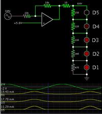
In regard to the led array, it operates between 7 and 9.2 V (approximate, for red led's).

It is wise to install a safety resistor for the led's.

Both the gain and the bias V at the non-inverting input need to be adjusted carefully.

If your input signal is strong, then your gain can be less than 1.

This simulation shows values that work for an input signal with amplitude +2 -2 V.


If your power supply is less than 9 V, you'll need to use fewer led's.

Another idea is to rectify (detect) the incoming radio signal. Then the op amp will not need to respond at 200 kHz.
 
ooooooo goodness
a lot of issue these internet available figures have . .
thats the reason i need a base to reach every aspect so as to shape up my dreams in own way . .

well lets discuss from the start of tank circuit
Would you please tell the ways which can make oscillations in a tank circuit ?
How can we get 190Khz & above ?
Does a transistorized designs work ?
 

The schematic is wrong. If you connect the coil to GND to pin 3 of a 555, you will kill it.
If you want to transmit a signal at 190 kHz over a short distance, learn how to make a transistor oscillator. You can use a pair of AM radios for this purpose. One can be used as a transmitter (oscillator only), with a ferrite rod antenna tuned to 190 kHz. The other as a receiver- you will have to tune the receiver to 190 kHz. Or you can use another ferrite rod antenna with a simple detector (as a crystal set) as the receiver.

An easier way is to use a LED or IR LED with chopped light, and a photodiode with an amplifier tuned to chopping frequency. A distance over 10 meters can be covered.


any replacement for ferrite rod ???
what is chopped light in practice ? any schematic of photodiode amplifier with a tuner ? how could i build ?
 

any replacement for ferrite rod ???
what is chopped light in practice ? any schematic of photodiode amplifier with a tuner ? how could i build ?

For a frequency like 190 kHz, ferrite rod antennas are small and easy to use. You can transmit simple commands over say twenty meters using a simple transistor oscillator as a transmitter and a crystal set as a receiver.
If the above looks too complex to you, chopped light is generated by e.. a 555 feeding a LED or IR LED. On receive side use a photodiode with an audio amplifier adjusted to the chopping frequency. Most often 1 kHz is used, or ~35 kHz in TV remote controls. Audio modulation or chopping allows to reduce the effect of ambient light and extends the range from a transmitter to a receiver. Some lenses or reflectors help too.
 
yeah i got it
Actual problem is availability of ferrite rod arrangments due to FM radios in present time thats why i am asking about the option . .

Well without this ferrite rod how much approx distance , the transmission is possible ?
Suppose i apply a simple small coil of 18-24 guage wire parallel to 27 pf on both side,then what could be the range ?

please help me in designing a simple transistor oscilator

Ferrite rod antennas are used in AM radios, not FM. At long waves (for 190kHz, the wave length is about 1600 m) you need a large antenna to radiate a reasonable power. With a ferrite rod antenna you can radiate more power than with a long wire.

I can guide you in small steps, but what you need is to read a textbook on basic electronics. Best of all, find the ARRL radio amateurs' Handbook where you can find almost all you need, from designing a transistor oscillator to making a radio or light sensor as you started asking for.


honour sir
o yeah that exactly i know that ferrite rod is used for the AM purpose as i ve made a project in 1995 with an AM 3 point (single tap) & a 2J gang capacitor , though i just copied from project book & got first prize too but the atmosphere leaved me unsatisfied enough as no one helped me in a deep study except my school & college level courses

But today parts like AM coil ferrite rod gang capacitor are not unavailable here or say purchasing from outside or online is a lil.bit cumbersome that i ll tell you later . . . why i said so . . . !

Too i can make an AM coil but again ferrite rod is an issue
Well i have a china made cheap remote control car which uses a small circuitry but transmit a range of 5 to 7 meters.Too reception unit is having a very small chip

Is there any substitute for ferrite rod ? like carbon rod from a dry cell ? i am guessing it just

Now for present i am trying to make transmission using FM and for a short distance first of all say 1 to 2 mtrs.or less for basic study . .
i don't know much and ya i agree i need to read basic & too need your help all the way for purpose so please please please help & i am visiting sites as per your suggestion

Is it possible with FM for a short distance transmission ?
 

When electronic hobbyists say that common inexpensive electronic parts are not available (they live on the moon?) then I tell them to do gardening instead of electronics.

My simple FM transmitter has a range of further than 2km to a sensitive hi-fi or car radio or across the street to a cheap FM radio from The Dollar Store.

The remote lock/unlock remote for my car has a range of about 150m.

My TV remote has a range of about 15m.


hehe gardening yo ! :D

actually sir these small shopkeepers bring in whole sale & for one or two person they don't take intrest or instead they charge their loss on us

Well coming to the point yeah i too found such car etc operating on FM
& all you said

so please tell about simple FM for firstly a short distance operation so that i may study the nature of it

I want to operate it like a wireless switch as we do in case of remote cars
 

Status
Not open for further replies.

Part and Inventory Search

Welcome to EDABoard.com

Sponsor

Back
Top