Continue to Site

Welcome to EDAboard.com

Welcome to our site! EDAboard.com is an international Electronics Discussion Forum focused on EDA software, circuits, schematics, books, theory, papers, asic, pld, 8051, DSP, Network, RF, Analog Design, PCB, Service Manuals... and a whole lot more! To participate you need to register. Registration is free. Click here to register now.

Check for drills in Eagle

Status
Not open for further replies.

Hest

Junior Member level 1
Joined
Jun 14, 2011
Messages
19
Helped
0
Reputation
0
Reaction score
0
Trophy points
1,281
Activity points
1,436
Hello

I have a problem with my PCB manufacturer, because they can't see my drills. I'm using a CAM found on their site http://iteadstudio.com/store/images/produce/PCB/PCB prototype/ITeadstudio_CAM.rar so I thought that would be it.

Also, when I only look at the drill layer, I can see the drills (image).
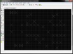
drills.jpg

How can I check if the drills are in the final files or not?
These are the files I get after the job is done.

files.jpg

When making the gerber file for drill (the .TXT?) only drills and holes are chosen in the right list, do I also need the dimension to be selected there and could that be the problem?

Hope you can guide me in the right direction.
 
Last edited:

Zip your manufacturing files and post them.

I assume you used the CAM processor to generate the Gerber files. You also need to generate the Excellon drill files. If you haven't done that, then you probably haven't generated them. You end up with three drill files with .dri, drd and .drl extensions. It is only really the .drd you need and it should look like this when loaded with a text editor:

Code:
%
M48
M72
T01C0.0157
T02C0.0276
T03C0.0354
T04C0.0360
T05C0.0394
T06C0.0433
T07C0.0787
T08C0.1614
%
T01
X9848Y8581
X10537Y11435
X7584Y14880
X6206Y14781
X6797Y17242
X8667Y17242
X8765Y17734
X9749Y18029
X10045Y17537
X9552Y16061
X12505Y18029
X13686Y18128
X15064Y18029
X15852Y16651
X17230Y18029
X15753Y19900
X14966Y20785
X14966Y21868
X15064Y24329
... etc

Keith.
 

I'm only using the CAM to make the files, so I don't have any other files.

On the manufactures site, it sais they need these files

Gerber files required:
Top layer: pcbname.GTL
Bottom layer: pcbname.GBL
Solder Stop Mask top: pcbname.GTS
Solder Stop Mask Bottom: pcbname.GBS
Silk Top: pcbname.GTO
Silk Bottom: pcbname.GBO
NC Drill: pcbname.TXT

So I'm not sure if they can/will use the other files or not. The .TXT file i get looks like this, but doesn't look right either. Can I create the Excellon files in Eagle and can I just save it as .TXT instead, as they want it?

G75*
G70*
%OFA0B0*%
%FSLAX24Y24*%
%IPPOS*%
%LPD*%
%AMOC8*
5,1,8,0,0,1.08239X$1,22.5*
%
%ADD10C,0.0000*%
%ADD11C,0.0040*%
%ADD12C,0.0010*%
D10*
X000000Y013500D02*
X000000Y000000D01*
etc....

Here are all my files View attachment led_blitz.rar
 

I found out how to make the Excellon drill files in Eagle.

Do you think thats the drill file the manufacturer wants instead of the other .TXT file? Not sure what the data in the old TXT file is for. But Looks correct now.

%
M48
M72
T01C0.0236
T02C0.0394
T03C0.0787
T04C0.1102
%
T01
X11601Y2101
X11601Y2101
... etc
 

Just rename the file you have created (starts % M48 etc) with .txt extension.

Keith.
 

Thanks for helping me out. The content of the file also makes alot more sence now.

I'll try and resend it to the manufacturer and see if they reject it again, but I think it's working now
 

Status
Not open for further replies.

Part and Inventory Search

Welcome to EDABoard.com

Sponsor

Back
Top