Continue to Site

Welcome to EDAboard.com

Welcome to our site! EDAboard.com is an international Electronics Discussion Forum focused on EDA software, circuits, schematics, books, theory, papers, asic, pld, 8051, DSP, Network, RF, Analog Design, PCB, Service Manuals... and a whole lot more! To participate you need to register. Registration is free. Click here to register now.

Changing viltage for SMPS By DAC

Status
Not open for further replies.

Paul GRIM

Junior Member level 1
Joined
Dec 5, 2014
Messages
16
Helped
0
Reputation
0
Reaction score
0
Trophy points
1
Activity points
97
Hello all,

I would like to vary the output voltage for my buck converter by a DAC.
V_DAC vary between 0 to 3.3V
V_HV vary between 0 to 100V
Can you help me how calculate the relation between V_DAC and V_HV :bang:
How i calculate R1, R2, R3 :?:

buck.PNG

Thank you
 

Hi,

is the OPAMP the feedback amplifier of your buck converter?


If so:
Voltage across R2 is constant 2.5V. No change in voltage no change in current, independent of output voltage.

The voltage across R1 should change 100V while the voltage across R3 changes 3.3V. No other voltage/current changes.
--> R1/R3 = 100V/3.3V --> R3 = R1 * 3.3V / 100V = 0.033 * R1

Output voltage will rise with falling DAC voltage.
U_out = 100V - (100/3.3) * U_DAC

Imagine U_DAC = 2.5V, then voltage across R3 is 0V, therfore current is 0mA.
The output voltage = 100V - (100/33) * 2.5V = 24.24V
Then current through R1 = current through R2

U across R2 = 2.5V,
U across R1 = 24.24V - 2.5V = 21.74.

Now R2 = 2.5V *R1 / 21,74V = 0.115 * R1

Klaus

***
Edit: Calculation error of R2
 
Hi Klaus,

Thank you for your answere :grin:
yes, the OPAMP is the feedback amplifier of my buck .

But if i simulate my circuit, i havn't a good value
for ex: R1=20K; R2=2.3K; R3=660

V_DAC=0 => Vout=100V
if V_DAC=3.3V => Vout=45V :?:
Have you an idea for this error ?

Thank's

Paul
 

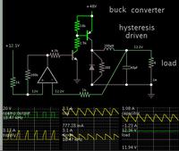
For comparison, here is my simulation of a regulated buck converter.


The op amp acts as a comparator. Hysteresis is added via positive feedback.

The op amp turns on when the load voltage drops. It shuts off when load voltage rises to the reference V at the input. A buck converter is an easy type to operate with this simple feedback.
 
Hi,

Maybe i have a calculation error.

For a real DAC the 600 Ohms may be a bit low.
Try twice the values.

I'll check my calculations in 12 hours.

Klaus
 
Hi,

I am checked your formulation and they are correct.
my output voltage vary if the V_dac vary :grin:
this relation is approuved in simulation (Uout=100V-(100/3.3)*Udac)

in our case if Udac=0 Uout=100V, is it possible to invert this relation (If Udac=0 Uout=0 and if Udac=3.3 Uout=100V) :thinker:

Thank you so much

Paul
 

Hi,

in our case if Udac=0 Uout=100V, is it possible to invert this relation (If Udac=0 Uout=0 and if Udac=3.3 Uout=100V)

.. with an inverting OPAMP at DAC output to change 0..3.3V --> 3.3V ... 0V

Klaus
 
Can you replace 2.5V ref with the DAC output? You can't otherwise do 0-3.3->0-100
 

Good remarque, but i havn't access to 2.5V ref voltage, it's internal of the chip
 

Hi,

Can you replace 2.5V ref with the DAC output? You can't otherwise do 0-3.3->0-100
Why not? Because of ghe supply rails?
Then just give the feedback resistor R1 a higher value to gain some headroom.

Klaus
 

Hi,


Why not? Because of ghe supply rails?
Then just give the feedback resistor R1 a higher value to gain some headroom.

Klaus

I meant he can't do it with his circuit. It looks like Paul got my point.
If Paul discloses which DAC maybe we can advise him how to save adding an inverter.
Is ghe a German swear word?
 

Hi,

A typo: "ghe" --> "the".

Klaus
 

Hi,

please see this figure
Capture.PNG

My PWM is controlled by an analogic controller,
The DAC generate juste a reference voltage.

Paul
 

It looks like it's possible to modify Vref from pin 11 but it is a risky business. Pin 11 is provided for C3 to balance C4. There are no guarantees that the error amp can take the common mode error and will response in a linear fashion. If you are making many of these circuits then you may run into troubles.

If you still want to try, measure the DC at pin 11 that it is 2.5V.
Select R8 R7 to give you 100V output.
Inject 1.25V to pin 11 or put resistor to ground that will take the voltage to 1.25V.
See if the output goes down to 50V.

BTW, if the 100V is sourcing low current it could be easier to do it with a linear amp instead of PWM.
 
Last edited:

Status
Not open for further replies.

Part and Inventory Search

Welcome to EDABoard.com

Sponsor

Back
Top