Continue to Site

Welcome to EDAboard.com

Welcome to our site! EDAboard.com is an international Electronics Discussion Forum focused on EDA software, circuits, schematics, books, theory, papers, asic, pld, 8051, DSP, Network, RF, Analog Design, PCB, Service Manuals... and a whole lot more! To participate you need to register. Registration is free. Click here to register now.

Car Side Marker / Indicator selector

Status
Not open for further replies.

BFAL

Newbie level 2
Joined
Nov 26, 2012
Messages
2
Helped
0
Reputation
0
Reaction score
0
Trophy points
1,281
Location
London UK
Activity points
1,331
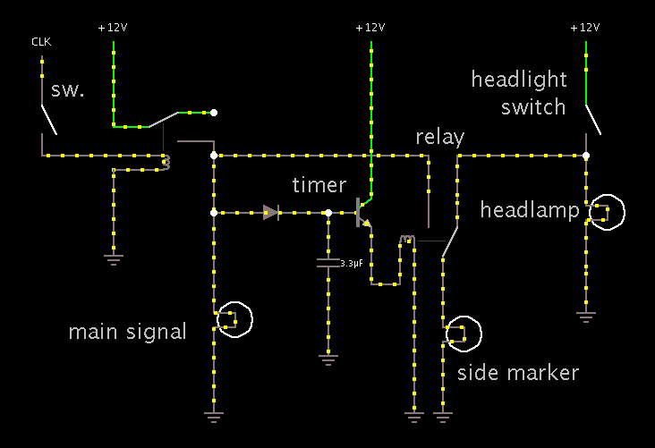
I have a Jeep Wrangler and the design of the Jeep means that the side wings (fenders) are wider than the headlamps. I live in the countryside and the width of the vehicle is very difficult to judge by oncoming motorists.

The Jeep is fitted with what US drivers would call side markers in the side of the front fender. These are amber lights which in the UK are used as direction indicator repeaters. I need help to design a circuit that operates the bulb as a sidemarker at night as well as a direction indicator.

The design should acomplish the following:-

In normal daytime operation, the side repeater would flash in time with the direction indicators as it does today
When the side lights (parking lights) are switched on, the side repeater would become a side marker and be turned on constantly
When the direction indicator is switched on with the side lights turned on the side repeater will flash in time with the direction indicator.

I worked out how to do this with relays except that the side repeater would work in the opposite time to the indicator bulb
i.e. When the indicator lamp is on, the side repeater would be off and vice-versa - although I understand this is allowed in North America this is not legal in the UK.

Design wise, when the side lights are off, the indicator could work as normal on a "pass through basis" although the two feeds would need to be separated to stop the main direction indicator bulb turning on when the sidelights are turned on
When the side lights are on, the side marker should be illuminated permanently.
When the direction indicator is turned on then the side marker needs to turn off in time with the indicator ( the earth could be disconnected rather than the live to acheive this if it is easier as the bulb is isolated from the car body) - some form of timed latch would be required so that when the indicator is turned off again the side marker remains switched on

The side repeater bulb is only 6 watts (12volt) so the current switching is not excessive - 2 amps from memory.

I hope somebody can help me out here with a design, I know payment is not appropriate on this forum but I'll happily make a moderate donation to charity for a solution to this for safety reasons. :smile:
 

It may be easier to hook up small bulbs (or bright LED's) to the headlight wires. With luck they will be small enough to sit inside the amber bubble next to the turn signal bulbs.

I have been trying a simulation. I can see you thought out the details as to what you want to hook up yet not interfere with normal operation of the turn signal.

Your new relay will be a SPDT type. The side marker will go to the common terminal. It will choose where it gets power from, either the headlamp or the turn signal. A timer circuit may be the best way to activate the relay when the turn signal comes on.

Have you been able to get to the wire that brings in the 'On' signal from the stalk on the steering column? The stalk you flip to signal a turn? It makes the flasher unit operate. If you can get at this wire, you can make your new relay cooperate with the existing wiring, possibly without the timer delay.

If not, however, you are on the right track as to installing a timer circuit. It will turn on when the flasher unit comes on. It will activate the new relay for a second or two, for as long as it receives positive pulses.

I like to use an animated simulator which is ideal for this sort of project. It's at:

www.falstad.com/circuit

Here is a screenshot:


If you click this link, it will open Falstad's website, load my simulation, and run it on your computer. (Click Allow to load the Java applet.)

https://tinyurl.com/bt4ujs4

Click the switches to operate it.

I may have guessed wrong about the wiring.

There will be the issue as to whether you must keep left and right wiring separate, or whether you can combine some devices.
 

Hi BradtheRad
many thanks for your quick reply.

so my observations and that is all they are as I think you have solved the issue.

1. Thought about using other lamps, but side repeaters must extinguish completely in the uk rather than be hi/lo which would happen with extra bulbs and side markers illuminated.

2. Finding the indicator switch feed won't help. Your diagram shows the indicator switch activating the flasher relay. The jeep is much more basic. The indicator flasher is constantly connected to the positive feed from the ignition to the common terminal of the indicator switch. The circuit is completed by the switch connecting this common switch feed to either the right hand or left hand indicator bulbs and flowing to ground. Hence the need for the timer.

3. Not important, but in the UK the side lamps also act as parking lamps so can be switched independently of the headlamps. Importantly your design uses the Normally Closed (NC) contacts of the relay so if left in park mode, there is no additional drain through the relay solenoid.

4. I couldn't make your demonstration work by folowing the link, I got a circuit, but it appears to be the standard one on the website.. but that is probably me.

5. I just want to test my understanding of the operation:-

When the side/headlights are turned on the sidemarkers illuminate via the NC relay contacts.
Regardless of the state of the sidemarkers (on or off) when the Indicator switch is turned on the initial pulse runs through the diode to the transistor switching the current to energise the relay and making the Normally Open (NO) contacts - the indicator circuit then operates as normal.
The capacitor holds charge during the "off" cycle of the indicator , it cannot discarge through the diode therefore the changeover relay stays connected and indicators flash the side repeater as normal. When the indicator is turned off the "On" pulse ceases, the capacitor discharges dropping the relay which then returns the contacts to the NC position.

I cannot see any way of sorting the two sides issue other than duplicating the circuit - but the componets are cheap so its no big deal.

6. Would adding a variable resistor between the transistor activation pin (can't remember what its called) and ground enable this to be adjusted so that it stays on long enough between indicator pulses but releases the relay relatively quickly after the indicator is turned off?

Finally, are there "standard" component numbers or values that you could recommend for this circuit please... the relay is easy and you give a value for the capacitor. In my day timers were operated by 555 ICs (which I see are still around!) and Amps were driven by 3055 transistors.

I will of course come back and confirm its working.

Best regards Bob
 

4. I couldn't make your demonstration work by folowing the link, I got a circuit, but it appears to be the standard one on the website.. but that is probably me.

Yes, the first link brings up the default circuit. Evidently with that one open, it prevents an incoming link from loading.

It should be possible to run my simulation by closing all the falstad.com windows, then clicking the link:

https://tinyurl.com/bt4ujs4

5. I just want to test my understanding of the operation:-

When the side/headlights are turned on the sidemarkers illuminate via the NC relay contacts.
Regardless of the state of the sidemarkers (on or off) when the Indicator switch is turned on the initial pulse runs through the diode to the transistor switching the current to energise the relay and making the Normally Open (NO) contacts - the indicator circuit then operates as normal.
The capacitor holds charge during the "off" cycle of the indicator , it cannot discarge through the diode therefore the changeover relay stays connected and indicators flash the side repeater as normal. When the indicator is turned off the "On" pulse ceases, the capacitor discharges dropping the relay which then returns the contacts to the NC position.

I cannot see any way of sorting the two sides issue other than duplicating the circuit - but the componets are cheap so its no big deal.

Yes, you're up to speed, I can tell.

I made several assumptions, such as which components are closer to ground, etc.

You may need to rearrange things to suit your vehicle. The simulator will let you do this, to see what will work as far as making left and right circuits cooperate.

6. Would adding a variable resistor between the transistor activation pin (can't remember what its called) and ground enable this to be adjusted so that it stays on long enough between indicator pulses but releases the relay relatively quickly after the indicator is turned off?

Yes, you will need to adjust values to obtain the right amount of delay. I inserted a basic peak detector (or sample-and-hold). The capacitor will probably need to be a much larger value (on the order of 470 uF to 2000 uF).

Or you can use a 555. Or you can use a mosfet. Etc.

Finally, are there "standard" component numbers or values that you could recommend for this circuit please... the relay is easy and you give a value for the capacitor. In my day timers were operated by 555 ICs (which I see are still around!) and Amps were driven by 3055 transistors.

The transistor can be general purpose. It must handle sufficient current to turn on the relay coil. I believe a small signal type is adequate. 2N3904, 2N2222, etc.

At first a 12V relay coil seems appropriate. However it depends on whether the transistor can deliver sufficient voltage/current. If not then a 9V relay may be called for.

As to what capacitor value to use, it will depend on how fast it discharges through the transistor, and through the relay coil. This will require experimentation. (I used a small uF value in the simulation, to reduce the wait.)
 

Status
Not open for further replies.

Part and Inventory Search

Welcome to EDABoard.com

Sponsor

Back
Top