Continue to Site

Welcome to EDAboard.com

Welcome to our site! EDAboard.com is an international Electronics Discussion Forum focused on EDA software, circuits, schematics, books, theory, papers, asic, pld, 8051, DSP, Network, RF, Analog Design, PCB, Service Manuals... and a whole lot more! To participate you need to register. Registration is free. Click here to register now.

Capacitors in parallel , only one gets damaged why

Status
Not open for further replies.

PrescottDan

Banned
Joined
May 1, 2014
Messages
119
Helped
0
Reputation
0
Reaction score
0
Trophy points
16
Activity points
0
Multiple capacitors with the same capacitance value and same voltage rate are in parallel but only one gets damaged and it's the same capacitor every time

Since all the capacitors have the same capacitance and same voltage rate , why would only one get damaged? and the same one?

They are in parallel using a bare wire

It's seems like one of the capacitors gets hit with in rush current or pulse spike first before the other ones, but how so when they all are in parallel

When you put multiple capacitors in parallel the ESR is lower?

Since the ESR is very low the In rush current or spike can damage the capacitors easier?

Does the Bare wire case delay to each capacitor in parallel?

- - - Updated - - -

Since all the capacitors aren't MATCHED , would this cause one capacitor out of the others to be HIT first with the in rush current or voltage spike before the others?

Or what is causes one of the capacitors to be HIT first by the in current current or voltage spike before the others?
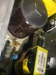
 

Putting big Caps in // is like putting small resistors (ESR) in //.

The smallest value ESR takes the biggest load current and forces film, laminant or plates to move and short if the ripple current exceeds specs.

- equalize the ESR by adding small power resistors to balance the current-sharing.
 

But larger capacitors will also have a larger dv/dt rating and therefore will handle larger inrush.

Btw I have never seen a capacitor fail simply because it was suddenly connected to the supply while discharged. (worst dv/dt case)
There may probably be repetitive over-currents. Provide more details.
 

In the 70's I used tantalum capacitors as local supply bypass capacitors on regulated and filtered DC supply voltages. ALL of the capacitors failed (blew up) after having the circuit powered up many times. Their voltage rating was 16V and were used on a 5V supply voltage. Fairly small electrolytic capacitors were used as replacements and they never failed.
 
Mil-std HDBK 217 defines the Reliability derating of all components including Caps. The ripple current derates reliability X faster in old electrolytics with increasing ripple current.

This is still true today for cheap parts but not the same for low and ultra low ESR parts, which are designed for higher ripple currents.

The solution today is choose parts for > rated ripple current of power supply at 100,120 Hz or choose parts with (lower ESR) for SMPS supplies.

That means the parts which do not spec ESR but give Ripple current specs @120Hz are good but not as low ESR as ultra low ESR Caps. (<10mΩ~)
 

Wouldn't we generally use ceramic capacitors for bypassing? Were ceramic capacitors not that cheap in the 70s?
 

It depends on ripple current and rise time. As you know Ic = C dv/dt for transients and bridge rectifiers produce pulse currents when conducting during the rise of ripple then supply current during the decay.

Since this is slow rise time, big electrolytics are adequate and the decay time is long <40ms so, 0.1mF per Watt on the output side are used to reduce rectifier ripple with care on ripple current rating.

Since SRF of big electrolytics is (poor) or low, the inductive impedance rises anove the ESR for f> SRF (self resonant freq) so then when step loads or spikes occur, 10 to 100nF is used in parallel to maintain low ESR over a wide bandwidth > 5 decades.

For Microwave < 50 pF special SMD ceramic is used to increase the SRF and reduce ESR.

For high slew rate SMPS, ultra low ESR electrolytics and for high V SMPS, plastic has the advantage of low ESR & low ESL and thus high SRF.

In some cases plastic and electrolytics are used for Low and high frequency, but plastic costs more per uF but rated for higher V.

Today low ESR ceramic SMD's are also popular. Very large ceramics SMT's are good but bad for PCB flex and stress cracks n ceramic.

Electrolytics are often selected from the best Japanese suppliers who take more care in material and process quality and root cause failure analysis for ongoing reliability. The components are often the highest stressed parts in any design. These are also advertised in the better PC MOBO's.

Big electrolytics are not as critical for LDO's except where ultra low current or dropout LDO's lose gain phase margin when excessive or insufficient ESR loads are used. thus these chips specify a limited range of ESR. This is very common on modern LDO's unlike the old school LM317's and 78xx LDO's with 2.5 V drop.
 

I still don't understand why out of all the capacitors in parallel why would one of them get HIT first with the in rush current, ripple current, current spike before the others

The capacitor that gets HIT first takes the in rush current/current spike while the other capacitors in parallel are charging?

What determines out of all the capacitors in parallel to make one of them get hit first before the others?
 

Two factors will determine the inrush:
1. ESR
2. ESL
Larger capacitors will generally have lower ESR but higher ESL, provided all are the same type, from the same manufacturer.
Why dont you specify what type of capacitors you are using, also their voltage rating, capacitance and the voltage across which they are connected.
 

Why dont you specify what type of capacitors you are using, also their voltage rating, capacitance and the voltage across which they are connected.

electrolytic capacitors at 220uf, at 16 volts i think

When the Solenoids coils turns off it creates an in rush current and voltage spike in a negative voltage i would think

This negative voltage or negative in rush current when the solenoids coil turns off

So I don't know the voltage or current is when the solenoid is turned off is
 

Solenoid current ON must be same used by snubber diode in reverse polarity across coil. the diode dumps the solenoid current when switched off.

If PS is not adequate for current, Cap ripple,will be excessive.

- details of solenoid specs and PS specs are critical to understand issue here. The ESR of the regulator or unregulated supply must be much lower than the solenoid,Rs. If using an unregulated bridge & cap to,drive,solenoid, then the secondary winding resistance of the transformer must be much lower than the solenoid coil resistance to avoid large cap,ripple current when turned on.
 

Solenoid current ON must be same used by snubber diode in reverse polarity across coil. the diode dumps the solenoid current when switched off.

There is no snubber diode across the coil

There is a series forward diode to the coil , 3 capacitors in parallel are in across the coil

The series forward bias diode to the coil is to charge the capacitors and coil when it's on, but when the input voltage is turned off, the coil discharges to the series diodes cathode to the capacitors that are in parallel to the coil

The 3 parallel capacitors are charged , when the coil is discharging, so the coils discharging an in rush current and voltage spike to 3 parallel caps that are charged

This might be a problem right?
 

This is what happens to Big caps with excessive ESR,as it happened today to my Samsung 43" TV after 5 Yrs.
image.jpg
The screen intensity was low and I suspected power supply.

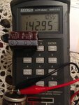
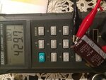
After inspection, Main AC to DC rectifier Cap was leaking and showed Capacitance reduction of 60% (143uF) and ESR increased from spec of 0.5Ω Typ to >10kΩ !! Typical failure mode.

I replaced 390uF 250V 105'C part with 440uF 250uF 105'C part which measured within+/-20% tolerance on the low side (429uF) ( typical mfg cost saving to produce on low side.)

AS shown below for bad and new Cap on RLC meter.
image.jpgimage.jpg

It worked and should last longer and runs cool with better ESR. (Tested at 120Hz 0.21Ohm on meter) Cost$5
 

The ESR of the regulator or unregulated supply must be much lower than the solenoid,Rs.

The Regulator IC chip has an ESR value?

The Solenoids coils resistance must be much lower then the power supplys ESR?

If using an unregulated bridge & cap to,drive,solenoid, then the secondary winding resistance of the transformer must be much lower than the solenoid coil resistance to avoid large cap,ripple current when turned on.

Why does the solenoids coil resistance need to be much lower then the secondary winding resistance of the AC line transformer?

If It's a regulated power supply, the solenoids coil resistance can be higher then the secondary winding resistance of the AC line transistor?
 

There is no snubber diode across the coil

There is a series forward diode to the coil , 3 capacitors in parallel are in across the coil

The series forward bias diode to the coil is to charge the capacitors and coil when it's on, but when the input voltage is turned off, the coil discharges to the series diodes cathode to the capacitors that are in parallel to the coil

The 3 parallel capacitors are charged , when the coil is discharging, so the coils discharging an in rush current and voltage spike to 3 parallel caps that are charged

This might be a problem right?


yes

this is a problem.

Just drive the solenoid with a switch and use reverse Power Diode on coil and small RFI cap 0.1uF and decouple from other circuits if required.
 

Just drive the solenoid with a switch and use reverse Power Diode on coil and small RFI cap 0.1uF and decouple from other circuits if required.

The Solenoid is driven by a Logic Gate to turn on and off the voltage to the coil of the solenoid

I will post the schematic of this circuit tomorrow , i thought i had it

yes , this is a problem.

What does the in rush current do to a charged capacitor?

When a coil is discharging it creates an "overshoot" of current and voltage?
 

It is still unclear to me as to how the diode, coil and the capacitors are connected. Why dont you upload a sketch
 

Status
Not open for further replies.

Part and Inventory Search

Welcome to EDABoard.com

Sponsor

Back
Top