Continue to Site

Welcome to EDAboard.com

Welcome to our site! EDAboard.com is an international Electronics Discussion Forum focused on EDA software, circuits, schematics, books, theory, papers, asic, pld, 8051, DSP, Network, RF, Analog Design, PCB, Service Manuals... and a whole lot more! To participate you need to register. Registration is free. Click here to register now.

Capacitor not smoothing the output of Full Wave Controlled Bridge Rectifier...

Status
Not open for further replies.

muhibraza

Member level 1
Member level 1
Joined
Oct 11, 2010
Messages
38
Helped
3
Reputation
6
Reaction score
3
Trophy points
1,288
Visit site
Activity points
1,578
Hello, I have implemented the following circuit but the expected output waveform is not there....

IMAG0170.jpg

I am triggering the SCR at 1 degree and then gradually I increase the firing angle with increments of 15 degrees up till 150 degrees....I expected the average voltage to be maximum at 1 degree with an almost smooth waveform and minimum at 150 degrees.... as I increase the firing angle, the output average voltage should decrease proportionally and the values should be in descending order.... but this the not the case here....the output average voltage starts descending from around 45 degrees instead of 1 degree and the waveform from 1 degree to 30 degrees contains large ripples....Am I doing something wrong or is that supposed to be like that ? And what do I do in order to conduct maximum at lower angles and minimum at higher angles ? Please Help.
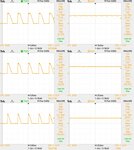
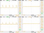
I am attaching the output waveforms that I recorded on 1,15,30,45,60,75,90,105,120,135 and 150º firing angles respectively (first row is on 1º, second row on 15º, third on 30º and so on)
the left ones are those without the capacitor in place, only the 50 Ohm resistor is present. And the right ones are those which were taken with capacitor in place (on the same firing angle)
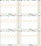
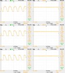
F0000TEK-tile.jpg
F0007TEK-tile.jpg
F0013TEK-tile.jpg
F0019TEK-tile.jpg
 

In My view rather than using only C-type capacitor I mean single capacitor ....Use either LC or CLC ( PI) type of filter.....it appears in your circuit that lot of ripple at higher voltage as you are using very low value of load resistance.... this is potentially because of capacitor is discharging faster as load is very low.....so preferred methodology will be used bit higher value ( may be electrolyte capacitor ) or used a combination like LC or CLC (PI) type filter.....

Good Luck
 

This sort of regulator only works with a choke input filter. Switching the diodes on before the positive peak, will allow the positive peak to charge the cap up to full peak voltage. This is because the charge time is low due to the low series resistance. Adding the choke causes the current to ramp up slowly, so it integrates the voltage over the full half cycles. Now a days its better to run the input side with ordinary diodes to charge the cap up to Vp, then use a switching transistor to chop the resulting DC and use a 10 micro henry choke and a 1 MF cap as the output filter! :)
Frank
 

so preferred methodology will be used bit higher value ( may be electrolyte capacitor ) or used a combination like LC or CLC (PI) type filter.....

Can you suggest any suitable values of L and C that would solve the problem in this circuit ?
 

Do you trigger/fire the SCRs with relatively narrow pulses?

Yes, the on time for the pulses is 500 u sec.... and we can see the output waveform without the capacitor it is just fine and it shows that SCRs are triggering pretty well with this pulse....I have also tried to trigger it with a burst of 4 pulses at a time each is on for 100 u sec.... response was almost the same... the problem actually starts when I connect the capacitor.... right now I m looking for some suitable values for L and C... I m going to use a CLC filter now
 

As you know, for an SCR to turn on, the voltage of its anode should be higher than of its cathode.
When you add a capacitor, a voltage is built on it. This creates a reverse voltage on the SCR on the time of the triggering. The SCR will trigger again only when it is positively polarized at the time of triggering.
The remedy of this is by widening the triggering pulse till it reaches up to 90 deg of each rectified half cycle.
 

Can any one provide me any information about how to wind an inductor of a specified value on a toroid ?
 

I am sorry, it seems you couldn't get what I said on post #8.

I got it now.

- - - Updated - - -

@KerimF:

by the way if I increase the pulse width then I cannot attain higher triggering angles.... I am actually making a battery charger that would increase or decrease the charging current as required so I need access to the higher triggering angles as well...
anyways for testing I would increase the pulse width too, but right now I want to check the output with CLC filter but for that I need to know the calculations etc for winding an inductor....
 

You are right.
But what I meant is that the leading edge of the trigerring pulse is delayed as you do for the narrow pulse.
Its trailing ledge should follow it (the end of the pulse) not before the 90 deg. of the half cycle.


For instance, I use a triac at the primary of the transformer to regulate the charging current. But as pointed out by other members here, I add a choke (with air gap) for DC current in series with the battery. If the voltage range of the mains power lines is rather wide, I use 2 or even 3 triacs (after adding 2 or 3 transformer terminals at the primary side) to avoid narrow high charging current pulses.
You can also use one triac, rated for high current, before the rectifier diodes. But in all cases a choke is needed. For my 100AH acid lead, I chose its inductance to be about 100uH for 20A charging current.
 

Status
Not open for further replies.

Part and Inventory Search

Welcome to EDABoard.com

Sponsor

Back
Top