Continue to Site

Welcome to EDAboard.com

Welcome to our site! EDAboard.com is an international Electronics Discussion Forum focused on EDA software, circuits, schematics, books, theory, papers, asic, pld, 8051, DSP, Network, RF, Analog Design, PCB, Service Manuals... and a whole lot more! To participate you need to register. Registration is free. Click here to register now.

[SOLVED] Capacitive Divider Impedance

Status
Not open for further replies.

marfirefly

Newbie level 3
Joined
Jan 9, 2016
Messages
4
Helped
0
Reputation
0
Reaction score
0
Trophy points
1
Activity points
49
cap-div-impedance.png
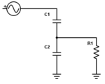
Hello all, this isn't really an application specific question I have so I'm not using specific components here, but really it's just a general theory question. When using a capacitive voltage divider and load resistor, how do you calculate the current leaving the AC source, or in other words, the impedance as seen by the AC source? More specifically, referring to the image above, do you calculate R1 as being in parallel with C2 or in series with the divider as a whole? Or, do you calculate R1 as being in parallel with C2?
 

I asume the AC source is connected to ground on the other side. Anyway, C2 and R1 are in parallel and the impedance of them in series with C1. So you have this:

TOTAL IMPEDANCE Ztotal=Z1+Z2||R1, so the AC current is Vac/Ztotal.
 
Status
Not open for further replies.

Part and Inventory Search

Welcome to EDABoard.com

Sponsor

Back
Top