Continue to Site

Welcome to EDAboard.com

Welcome to our site! EDAboard.com is an international Electronics Discussion Forum focused on EDA software, circuits, schematics, books, theory, papers, asic, pld, 8051, DSP, Network, RF, Analog Design, PCB, Service Manuals... and a whole lot more! To participate you need to register. Registration is free. Click here to register now.

Capacitive coupled LED

umery2k75

Advanced Member level 1
Joined
Apr 19, 2006
Messages
434
Helped
41
Reputation
80
Reaction score
15
Trophy points
1,298
Location
Pakistan
Activity points
5,748
Hello everyone,
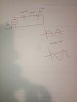
I wanted to experiment if I could drive an LED 3mm RED 1.8V forward bias voltage through a capacitor, so I connect function generator on HighZ on 5Vpp 300KHz connect it with different capacitors non-polar and polar and in series with resistor and a LED. All small non-polar capacitors like 0.1uf or 0.01uF shifts down the AC waveform just enough so the LED doesn't turns on, later I experiment with polar capacitor 100uF 25V, I was able to see the LED turning bright but eventually the AC wave shift downs and light intensity lowers down, I increase Vpp slowly then I can see bright light again then light intensity lower down. When I turned my Vpp to my original position 4.5Vpp coming from 10Vpp. I can see LED turns off completely and my majority AC waveforms has shifted down in negative and then I have to remove the capacitor - then short it and put it back again, then it starts to work again. Can anybody shed some light.


Experiment video
 

Attachments

  • IMG20230201031359.jpg
    IMG20230201031359.jpg
    2.8 MB · Views: 30

danadakk

Advanced Member level 5
Joined
Mar 26, 2018
Messages
2,296
Helped
351
Reputation
720
Reaction score
530
Trophy points
113
Activity points
10,092
Your LED is a diode in function, so when you start with a discharged cap, it slowly
charges up and acquires a V. A V no longer available to turn on LED. Note I simed
this with a regular diodes as I do not have a LED in simulator. 2 diodes to sim a red
LED turned on V.

1675208316458.png


Green is diode current.


Regards, Dana.
 
Last edited:

KlausST

Super Moderator
Staff member
Advanced Member level 7
Joined
Apr 17, 2014
Messages
23,281
Helped
4,742
Reputation
9,505
Reaction score
5,130
Trophy points
1,393
Activity points
154,237
Hi,

A LED works with DC current.
But a (series connected) capacitor blocks DC current.

Thus you can only see the LED light when the capacitor gets charged. As soon as it is charged high enough the DC current stops.

Try to use connect a anti parallel diode to the LED. Thus AC current can flow. In one direction through the LED, in the other direction through the diode.

Klaus
 

FvM

Super Moderator
Staff member
Advanced Member level 7
Joined
Jan 22, 2008
Messages
51,003
Helped
14,633
Reputation
29,542
Reaction score
13,742
Trophy points
1,393
Location
Bochum, Germany
Activity points
291,794
Did you review a LED datasheet? It has relative low reverse breakdown voltage. Without antiparallel diode, the LED can be easily destroyed in your experiment.
 

danadakk

Advanced Member level 5
Joined
Mar 26, 2018
Messages
2,296
Helped
351
Reputation
720
Reaction score
530
Trophy points
113
Activity points
10,092
Did you review a LED datasheet? It has relative low reverse breakdown voltage. Without antiparallel diode, the LED can be easily destroyed in your experiment.

Looked at several datasheets, Blue, Red seem to have 5V as max reverse voltage. So no
margin in design. That spec was, in some datasheets, at room temp. Even less margin in
actual use......

Using a reverse diode to protect LED, can function generator handle driving a forward
biased diode directly ? Consult the datasheet for the f() generator to make sure it
can manage, that is operative word of the day.


Regards, Dana.
 

LaTeX Commands Quick-Menu:

Similar threads

Part and Inventory Search

Welcome to EDABoard.com

Sponsor

Top