Continue to Site

Welcome to EDAboard.com

Welcome to our site! EDAboard.com is an international Electronics Discussion Forum focused on EDA software, circuits, schematics, books, theory, papers, asic, pld, 8051, DSP, Network, RF, Analog Design, PCB, Service Manuals... and a whole lot more! To participate you need to register. Registration is free. Click here to register now.

[PIC] can we make 3 phase sensing using pic 16f628

Status
Not open for further replies.

hamidooon

Junior Member level 1
Joined
Dec 10, 2015
Messages
16
Helped
2
Reputation
4
Reaction score
2
Trophy points
3
Activity points
169
Hello all,
I working on project that ons the relay when 3 phases are on and offs the relay when 1 or 2 or all 3 phases are faulty.
I need direct 3 phase connectins to pic 16f628 no tarnsformers , optocouplers etc. I attached one image that tells when 3 phases are available then what happens. See image bellow P_20160102_220748.jpg
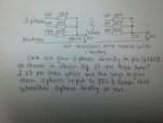
Can i use pics internal comparator for this logic?
Please give any resource for 3 phase detection usimg pic 16f628.
How can reduce 440 v ac to 5 v dc without transformer?
Give ckt that sense 3 phase and on off the relay....
 

If you don't need isolation from mains then you can use resistors and a diode to get 5V to adc input if your PIC has adc. Also you cen feed it to Comparator. my advise is use PIC18F46K22 or PIC18F26K22 which has 3 INTx pins. Use Optocouplers and resistors and interface the o/p of opto isolators to INTx pins and if interrupt is detected it means phase is present but if you want to take decision based on phase voltage then you have to use 3 ADC channels.
 

Provided you can connect the PIC VSS to the neutral wire it's easy, just use resistive voltage dividers to reduce the phase wires to within PIC VDD and clamp the signal so it can not go negative or higher han VDD (use a zener diode). Each phase will then see a logic signal of almost half one cycle. Pick one as the reference (zero time) and start a timer when either the rising or falling edge of the signal is found, then see how long it takes for the other two signals to follow it. If the delay is outside the allowed time, assume that phase has failed.

Something to watch out for:
Monitoring the voltage alone may not detect a missing phase because it may be re-created by a device downstream of the power break. For example, if you were monitoring at the terminals of a 3-phase motor and the power to one phase died, the motor terminal for that phase would still carry voltage created from the connection to the other two phases. If you can monitor the current along the phase wire instead of voltage it will give a better indication as no current will flow through a broken conection.

If the VSS is tied to neutral you can use a capacitive voltage dropper and rectifier to create the 5V PIC supply. If you need it to be fail-safe, derive 5V from all three phase wires and not just one. If you power it from just one phase, it will always be the one that fails first!

Brian.
 

20141231180003.jpg
Can we make this type of comparator using pic 16f628?
Please provide c code for comparator of pic ic..
 

The data sheet clearly shows how to use the internal comparator module but as I stated earlier, monitoring the phase voltage like that is unreliable. If you have to monitor the phase voltages, use the relative time shift of the phases to detect their presence, not their combined voltage. It's easy with a 16F628 and it does not use the comparator module.

Looking at the diagram you posted, consider what would happen if one or two phases failed, the comparator could still be adjusted to show all was OK. The circuit also requires a stabilized power source of about 18V to be capable of operating a relay like that, as shown it will not work from 12V. It is poorly designed for several reasons.

Brian.
 

If i convert voltage at point D to 5v Dc using zener diode , can this voltage is safe to interface with pic ic?
I see one ckt whichuses pic 16f628 and that sense three phase and detect which phase is faulty.3 phases are connected to 3 port pins of pic ic through 10k resistors to sense current across 3 resistors.if anybody has idea to connect 3 phase directly to pic using voltage sensing method then give me...
 

Hi,

How should your circuit work?

If voltage on all three lines is off, then obviously the voltage on point "D" is zero.

But if all three voltages are present, then the voltage at point "D" is zero also.

Only when there is unsymmetry, or one or two inputs are missing, then there is voltage at point "D".

Decide, if you want it to work like this.

Klaus
Yes i want like that if all phasese are off then voltage at pt D is 0
And all phases are present voltage at point D is also Zero.
Only if phase fault then voltage at point D is high can you help to build code.
I draw a schematic in proteus .it will be post soon...
 

Status
Not open for further replies.

Part and Inventory Search

Welcome to EDABoard.com

Sponsor

Back
Top