Continue to Site

Welcome to EDAboard.com

Welcome to our site! EDAboard.com is an international Electronics Discussion Forum focused on EDA software, circuits, schematics, books, theory, papers, asic, pld, 8051, DSP, Network, RF, Analog Design, PCB, Service Manuals... and a whole lot more! To participate you need to register. Registration is free. Click here to register now.

CAN Interfacing to communicate to ECU of a vehicle using PIC micro-controller

Status
Not open for further replies.

ChansAlive

Member level 3
Member level 3
Joined
Jul 8, 2013
Messages
55
Helped
2
Reputation
4
Reaction score
2
Trophy points
8
Visit site
Activity points
449
Hi
I want to communicate to the ECU of a vehicle to display few information on an LCD. I want to interface through CAN. I'm thinking to use PIC microcontroller. Also I'm in privilage to program the ECU too. Can anyone suggest me a possible low cost implementation? Also please help me how to transmit and recieve information through CAN.
Hope someone could help...
 

@Jinzpaul4u
Thanks for the post. But more than getting the required components, I want to know the details we have to check while implementing CAN and how it is programmed. What are the things we should take care of...
 

Hello there,


Try to study these attachments and revert back me.

Best regards,
 

Attachments

  • CE401_ECAN_Mode0_with_Baud.zip
    49.8 KB · Views: 199
  • CE034_CAN_Loopback_14aug09.zip
    21.3 KB · Views: 169
  • CE228_ECAN_FIFO_120309.zip
    57 KB · Views: 164
I have read about mikroC compiler. I could use only MPlab free version. with that I want to program a dsPIC controller for CAN implementation. I want to select a proper controller too. I hav confusion with dsPICf and dsPICe. what is the difference between them. I want to use e series because it is relatively less costly for CAN implementation. Can someone comment on this.
 

Hi
I want to communicate to the ECU of a vehicle to display few information on an LCD. I want to interface through CAN. I'm thinking to use PIC microcontroller. Also I'm in privilage to program the ECU too. Can anyone suggest me a possible low cost implementation? Also please help me how to transmit and recieve information through CAN.
Hope someone could help...

Which car ?

Look to use dedicated software and CAN interface for that car.


Also I'm in privilage to program the ECU too.

If you dont know what you are doing, better skip programming of ECU.


I have read about mikroC compiler. I could use only MPlab free version. with that I want to program a dsPIC controller for CAN implementation. I want to select a proper controller too. I hav confusion with dsPICf and dsPICe. what is the difference between them. I want to use e series because it is relatively less costly for CAN implementation. Can someone comment on this.


You can use MikroC for free but code is limited to 2KB of code data, if you need more then that, than you should get licence.

MikroC Pro for PIC CAN Library
https://www.mikroe.com/download/eng/documents/compilers/mikroc/pro/pic/help/can_library.htm

MikroC Pro for dsPIC CAN Library
**broken link removed**


PIC24F: Low Power
**broken link removed**

PIC24H/E: Highest Performance
**broken link removed**


NEW-16-bit-graphic_large.jpg


Best regards,
Peter

:wink:
 
@tpetar
Thanks very much for the post. I think my code will go more than 2KB. It includes this communication interface, controlling the display, some touch inputs and want to interact with smartphone through bluetooth. This is why I thought, I need MPLab IDE. I need to study how to use MPLab to programm MPLab. I'm thinking to use dsPIC33EP32GP503 with 25 I/O pins. I want to implement CAN for communication. I'm thinking to use some CAN ID to transfer the information to and from the ECU. I have not implemented CAN before. So I want to learn from the basic steps and requirements to implement the interface. I want to know upto the of process of sending some command from the ECU and receiving some data. The data which I need to send will be decided and configured myself(It is because I'm am in privilage to program ECU to get the required information). This display is not a tester, but a periphery required for the ECU. there will be other nodes also connected to the ECU too. I hope my situation is clear now.
 

I want to communicate to the ECU of a vehicle to display few information on an LCD. I want to interface through CAN. I'm thinking to use PIC microcontroller. Also I'm in privilage to program the ECU too. Can anyone suggest me a possible low cost implementation? Also please help me how to transmit and recieve information through CAN.

Unfortunately, it may not be as simple as implementing a CAN interface, the complexity of such a project depends largely on the make, model and year of the vehicle as well as the original import country in some cases.

While I have a considerable amount of experience with this issue, this is a complex topic which could easily fill several textbooks, discussing it in a venue such as this forum will be a challenge.

I should also state my experience is from the viewpoint of the US car market, as such the situation in your locale may differ.

However, as the US is one of the largest car markets, I suspect standards implemented in the US have had an impact globally.


To give you an idea of the challenges you face with such a project, consider events of the past couple of decades.


Automobiles were not mandated to utilize CAN (ISO 15765) until January 1, 2008, therefore automobiles manufactured before this date utilized a myriad of communication protocols.

These protocols are commonly referred to as pre-CAN, the three most commonly used were as follows:

SAE J1850 PWM - Utilized primarily by Ford

SAE J1850 VPW - Utilized primarily by General Motors

ISO 9141-2 - Utilized by Chrysler, European and many Asian Imports


Fortunately, another standard, On-Board Diagnostic II (OBD-II), mandated the use of the OBD-II interface for all automobiles manufactured after January 1, 1996.

The OBD-II connector (J1962) provides 16-pins for standardized access to the above three protocols, a fourth ISO 14230 KWP2000, and of course CAN (ISO 15765).


The European Union implemented their own version, EOBD, and mandated its use for gasoline vehicles manufactured in 2001 and diesel vehicles in 2004.

The Japanese have also implemented their own version, JOBD.


Now considering the lifespan of an average automobile, the fact is, most vehicles on the road today do not utilize the CAN (ISO 15765) protocol, but one of the other three communication protocols listed above or a fifth protocol, ISO 14230 KWP2000.


However, there are several alternatives to designing and building an OBD analyzer for use with the majority of automobiles in service today.


Anyway, hopefully this sheds some light of the subject and I will be more than happy to advise you as to your options.


BigDog
 
@JinzPual4u
Thanks for the files. It is very helpful. Unless I get the idea about the implementation, I don't think I will understand it completely. I'm trying to study it. I don't know which mode I should use for this kind of communication...
@BigDog
First of all, Thanks for the post. Here in my project, I'm not using the OBD pin slots. I will be directly connecting to the ECU. onsider that I know everything about the ECU. I need maximum of 8 byte data from the ECU and need to send some 5 byte to the ECU. I will assign som CAN ID to the message my self according to the priority. This CAN in the ECU is used for flashing of the ECU. So design should make sure that it won't affect the flashing process, since my display will always be connected to the ECU. Now I think my situation is almost like a mc-mc CAN communication. I am using a transceiver here. But I'm not sure how to implement the transceiver to a mc with in-built CAN module. Will the CAN module can be configured to work only as a CAN controller or is there any dsPIC IC which have just CAN controller(in order to reduce cost)?
Please help me...
 

First of all, Thanks for the post. Here in my project, I'm not using the OBD pin slots. I will be directly connecting to the ECU. onsider that I know everything about the ECU.

Is this an ECU of your design?

If not who is the manufacturer and its manufacture date?

Do you know for certain it has the CAN (ISO 15765)?


Will the CAN module can be configured to work only as a CAN controller or is there any dsPIC IC which have just CAN controller(in order to reduce cost)?

There are a number of PICs available which offer an embedded CAN module, they only require a CAN Transceiver such as the **broken link removed** or the newer **broken link removed**.

The PIC18, PIC24, dsPIC and PIC32 series all offer models which have an embedded CAN module.

Why are you considering the dsPIC? Are there other tasks which require digital signal processing?

What type of display are you planning to use, monochrome or color LCD?

BigDog
 
@BigDog
Thanks for the post.
Is this an ECU of your design?

If not who is the manufacturer and its manufacture date?

Do you know for certain it has the CAN (ISO 15765)?

This is not my design. But I can know all the details of the ECU. This is not implemented yet and is not the main ECU in the vehicle. This will be an added ECU to the vehicle to control certain fuel operations. The CAN available is based on ISO11898.

How can we interface a CAN module in dsPIC33EP to MCP2551 controller? Can the Module be configured not to use the built in transceiver?

I'm using 16 x 2 LCD backlit display. I'm using this inorder to provide for future enhancement in the product. At present there are few touch switches and I want to interface to bluetooth module.

- - - Updated - - -

What is the difference between MCP2551 and MCP2561 except that the latter is the newer one? They say that there is a split pin available but I don't understand its use. The reason for all these doubts is that I don't have any practical implementation experience. I hope you all could help me understand this. This project actually assigned to me as a part of my project work.
 

This is not my design. But I can know all the details of the ECU. This is not implemented yet and is not the main ECU in the vehicle. This will be an added ECU to the vehicle to control certain fuel operations. The CAN available is based on ISO11898.

If you require this custom ECU have the ability to upgrade its Flash, you will need to implement a CAN bootloader?

Silabs AN534 CAN BOOTLOADER

Microchip CAN Bootloader

How can we interface a CAN module in dsPIC33EP to MCP2551 controller?

It is fairly straight forward.

There are several dsPIC33EP which offer one or more embedded CAN module, use the parametric search or examine the attached file below.

dsPIC33EP with at least one embedded CAN module

CAN communication between two dsPIC

Can the Module be configured not to use the built in transceiver?

PIC do not have a builtin CAN transceiver, they must be used in conjunction with an external CAN transceiver like the MCP2551 or the newer MCP2561.

Attempting to connect a PIC directly to the CAN bus will result in the PIC being damaged and traffic on the bus disrupted.

I'm using 16 x 2 LCD backlit display. I'm using this inorder to provide for future enhancement in the product. At present there are few touch switches and I want to interface to bluetooth module.

Well that is really not an issue, there are more than enough I/O to drive both a 16x2 LCD and a bluetooth module.

BigDog
 

Attachments

  • dsPIC33E-2013-07-23.zip
    2.2 KB · Views: 131
@BigDog
Flashing is not a concern for me. There are others who would deal with it. I just want to to know how to implement a CAN connection. What are its requirements.
My concerns are:
The ECU supports CAN and I know the pin too. Shall I directly connect the CAN transceiver to those pins?

What are the software description I should follow? If the dsPIC supports CAN, can I just initialize all module for CAN and start sending the request to the ECU?

In short I'm not sure how to implement a CAN communication interface.
Please help me in understanding how to implement a CAN(iso11898) interface for mc communication.
 

What is the difference between MCP2551 and MCP2561 except that the latter is the newer one? They say that there is a split pin available but I don't understand its use.

The MCP2561 supports a newer revision of ISO11898-5, directly supports split bus termination and offer a few more safety features. For your application you should be able to use the MCP2551, if you wish to save some money and will most likely use Standard Termination not Split Termination.

The "split pin" offers direct support for split bus termination.

Reference: AN228 A CAN Physical Layer Discussion, Section: BUS TERMINATION, Page: 9
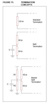
BUS TERMINATION

Bus termination is used to minimize signal reflection on
the bus. ISO-11898 requires that the CAN bus have a
nominal characteristic line impedance of 120Ω. There-
fore, the typical terminating resistor value for each end
of the bus is 120Ω. There are a few different termination
methods used to help increase EMC performance (see
Figure 11).

1. Standard Termination
2. Split Termination
3. Biased Split Termination

Standard Termination

As the name implies, this termination uses a single
120Ω resistor at each end of the bus. This method is
acceptable in many CAN systems.

Split Termination

Split termination is a concept that is growing in popular-
ity because emission reduction can be achieved very
easily. Split termination is a modified standard termina-
tion in which the single 120Ω resistor on each end of
the bus is split into two 60Ω resistors, with a bypass
capacitor tied between the resistors and to ground. The
two resistors should match as close as possible.

Biased Split Termination

This termination method is used to maintain the com-
mon mode recessive voltage at a constant value,
thereby increasing EMC performance. This circuit is
the same as the split termination with the addition of a
voltage divider circuit to achieve a voltage of Vdd/2
between the two 60Ωresistors (see Figure 11)


The ECU supports CAN and I know the pin too. Shall I directly connect the CAN transceiver to those pins?

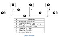
Yes, it is fairly straight forward, CANL is conected to the CANL side of the bus and CANH is connected to the CANH side of the bus.

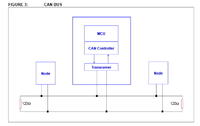
The transceiver pictured in the image below would be the MCP2551 or MCP2561, the node on either side of the central node could be the ECU.


What are the software description I should follow? If the dsPIC supports CAN, can I just initialize all module for CAN and start sending the request to the ECU?

Microchip provides a free library by which to utilize the ECAN controller module of the dsPIC33EP, it is not difficult to configure.

Study the document:

A CAN Physical Layer Discussion

And post any question you may have concerning the CAN physical layer.


I'll see if I can find a good code example of configuring the ECAN controller module.


BigDog
 
@BigDog
Thanks very much. :)
I will study the documents... It is really very helpful...
I will get back to you...
Thanks once again...
Regards
Athul
 

The following diagram may provide a clear description of a typical CAN bus with CANL and CANH clearly designated:


And the following paper is quite informative:

Controller Area Networks For Vehicles

BigDog
 
I referred the documents, it is very informative. Fortunately I got the hardware implementation of CAN. But I need the software description required to implement CAN. I'm using MPLAB X IDE and installed XC16 compiler. header files for CAN is available in the folder. But in source file(in the installation directory) I don't know which all file I should add. Also I don't know how to configure the header for the requirement. Can any give some suggestion to find those information...
 

Status
Not open for further replies.

Part and Inventory Search

Welcome to EDABoard.com

Sponsor

Back
Top