Continue to Site

Welcome to EDAboard.com

Welcome to our site! EDAboard.com is an international Electronics Discussion Forum focused on EDA software, circuits, schematics, books, theory, papers, asic, pld, 8051, DSP, Network, RF, Analog Design, PCB, Service Manuals... and a whole lot more! To participate you need to register. Registration is free. Click here to register now.

can i use a single port as input but some time output in the same program

Status
Not open for further replies.

thannara123

Advanced Member level 5
Joined
Jan 7, 2010
Messages
1,580
Helped
122
Reputation
244
Reaction score
114
Trophy points
1,353
Location
India
Activity points
10,384
Hello ,
can i use a single port(P1.0) as input but some time output in the same program
please help me thanks in advance
 

can i get an example in c
how port initlize
for example P1 =0x00; // output
then how it will make input after running some codes ?
 

Hai i have just copied and modified a bit from the blink LED example

/* BLINKY.C - LED Flasher for the Keil MCBx51 Evaluation Board with 80C51 device*/

#include <REGX51.H>

// When you have enabled the option Stop Program Execution with Serial
// Interrupt, the Monitor-51 uses the serial interrupt of the UART.
// It is therefore required to reserve the memory locations for the interrupt
// vector. You can do this by adding one of the following code lines:

// char code reserve [3] _at_ 0x23; // when using on-chip UART for communication
// char code reserve [3] _at_ 0x3; // when using off-chip UART for communication

void wait (void) { /* wait function */
; /* only to delay for LED flashes */
}

void main (void) {
unsigned int i; /* Delay var */
unsigned char j,read; /* LED var */

while (1) { /* Loop forever */
for (j=0x01; j< 0x80; j<<=1) { /* Blink LED 0, 1, 2, 3, 4, 5, 6 */
P1 = j; /* Output to LED Port */
for (i = 0; i < 10000; i++) { /* Delay for 10000 Counts */
wait (); /* call wait function */
}
}
P1 = 0xFF;//configure to input port
read = P1;//read the pins
P1 = 0x00;//configure to output port
for (j=0x80; j> 0x01; j>>=1) { /* Blink LED 6, 5, 4, 3, 2, 1 */
P1 = j; /* Output to LED Port */
for (i = 0; i < 10000; i++) { /* Delay for 10000 Counts */
wait (); /* call wait function */
}
}
}
}

Compile and open this program in your keil software, go to debug mode and select the peripheral port 1 and execute it step by step. When you reach the step where the port is configured to input port, carefully you unselect the data from pins (in the small port window). Refer the image. Now your port has been written to FF but the pins are holding some value. When you read the port in the next step, you read the value of pin not the port.


Thanks
 

thanks karthikkrv85 , i didn't get well
when P1 =0xff ; at this time why the output dont gets
 

thanks karthikkrv85 , i didn't get well
when P1 =0xff ; at this time why the output dont gets

I think we get the output. I mean we can send data.

When you write 0x00, the port pins doesn't listen to the external devices. Because when you write 0x00, the FET switch is activated and the port pin gets connected to gnd. During this time the external device send any information, will gets grounded. And when you read, the data also zero

But when you write 0xff, the FET switch is deactivated. So the internal pull up voltage, search for the low resistance path. Now if the external device send a logic 1 or logic 0, the pin voltage appears as it is to read.

There is no condition that you cant send any data during the input mode. you can send if the external device data is not important to you and the device expects the input from you.

In simple words, when you configure to output port, the pins are in your control. But when you configure to input port, the the pins are in external device control, who decides what should be the value

Am i confusing you still?

---------- Post added at 13:07 ---------- Previous post was at 13:01 ----------

I think the following image also helps you

 
yes please explain
thanks in advance

Hope the following information will clear your doubt

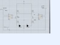
Consider you have 2 microcontrollers and P1.0 of both micro controllers are tied together just as shown in the image. (Gave just for example)

Lets consider one of the microcontroller as master and another as slave.

Now if we wants to transmit a data from master then we need to configure the master to output port. But what is the point of having a master without a slave in listener mode? So we configure the slave to input mode.

Now the circuits behaviour will become as follows,

output port:

master section:

1. master flip flop gets a logic low as input (D pin)
2. Q_bar becomes high and the FET Q1 gets activated
3. Because the master side FET is activated, the VCC passes via R1, R2, Q1, R3 and D1 towards gnd.
4. Now your port pin (drain) voltage becomes zero.

slave section:

1. slave flip flop gets a logic high as input (D pin)
2. Q_bar becomes low and the FET gets deactivated
3. Now when the slave reads the port pin (drain) voltage, it reads zero


If the master sends 1, vcc searches the low resistance. But both FETs are now deactivated. Now if the slave reads the port pin, it reads the voltage as logic high.

When slave is in listening mode (input mode), the master is the master of the port pin. What the master decides is the output of the port pin.

Input port:

Now if you want to receive a data from slave then you need to configure the master to input port. And we configure the slave to output mode.

Now the circuits behaviour will become as follows,

master section:

1. master flip flop gets a logic high as input (D pin)
2. Q_bar becomes low and the FET gets deactivated
3. Because the master side FET is deactivated, the VCC searches the low resistance path.

slave section:

1. slave flip flop gets a logic low as input (D pin)
2. Q_bar becomes high and the FET gets activated
3. Now if the master reads the port pin (drain) voltage, it reads zero because the port pin's fate has been under the control of slave now.

Your question is why cant the master send the output when the master in configured as input. Actual answer is we can do it but you are violating the listener mode. Because When slave transmits, it will be in output mode (creates low resistance path) and if the master also transmits at that time, creates another low resistance path. So you will not get synchronised to receive the data from slave. If the slaves goes to listening mode, may be you can transmit but again you falls into one of the above condition.


Thanks
karthikkr
 
Last edited:

Status
Not open for further replies.

Part and Inventory Search

Welcome to EDABoard.com

Sponsor

Back
Top