deathbybear
Newbie level 2
Hey everybody!
I'm working on a weird little project, and I've hit a wall. There are five lights inside a box, all of which I want to control from a single master dimmer. I'm using 12v auto lights and sockets for the lights themselves - like these - Amazon.com: Sylvania 3057LL BP Long Life Miniature Incandescent Lamp: Automotive
For power, I am using a 500w computer power supply, which is supposedly capable of pushing up to 32A at 12v.
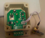
I got this 12v dimmer, which was rated for 8A - **broken link removed** - though I paid about 3x as much for it. :x
So, I wired everything together using a configuration like the attached image below. Basically: Power => Dimmer => Hub => 5 Lights/Switches
**broken link removed**
This didn't work. If I have the dimmer turned all the way up, all of the lights turn off and on with the switches, and all juice seem to flow fine. The problems come when I start trying to use the actual dimmer. If one or two lights are on, it will dim them from 0 to 100% without problem, but as soon as I attempt to dim 3 or more lights, something fails (presumably the dimmer) and the whole power supply shuts off. Not ideal!
My assumption is that the dimmer itself is just not capable of handling that much power. I tried to track down a 12v dimmer that would be able to handle more juice, but the only one I could find is $100 and you have to use a SPDT toggle. I really want to keep the rotary potentiometer for the dimming, and I really want to keep it set up so one dimmer is controlling all five lights.
So I came up with the idea I diagrammed out below, where basically I would use five separate dimmers, each controlling its own switch/light, but that each of the dimmers would be controlled using a single potentiometer. To accomplish this, I would just wire together the "like wires" from each dimmer's potentiometer, and wire each cluster back to a single master potentiometer. Hopefully the diagram will make this make more sense.
**broken link removed**
I guess my question is - will this work? Before I go spending $50 on four more dimmers and start cutting up the wires, I wanted to make sure this was even reasonable. Logically it seems to work for me, but there are usually factors i'm not considering. If it isn't obvious already, I'm already messing around in an area well beyond my knowledge level with all of this stuff, and just trying to figure it out as I go.
If I can't do it this way, are there any ideas for how I might be able to accomplish what I'm trying to accomplish.
Thanks for your time and any help you might be able to give me!
Jason
