Continue to Site

Welcome to EDAboard.com

Welcome to our site! EDAboard.com is an international Electronics Discussion Forum focused on EDA software, circuits, schematics, books, theory, papers, asic, pld, 8051, DSP, Network, RF, Analog Design, PCB, Service Manuals... and a whole lot more! To participate you need to register. Registration is free. Click here to register now.

CAN BUS physical layer problems

Status
Not open for further replies.

llima

Newbie level 4
Joined
Jan 2, 2012
Messages
6
Helped
0
Reputation
0
Reaction score
0
Trophy points
1,281
Activity points
1,338
Hello,

I have a project were several boards connect to each other using a CAN bus, however, I am having problems with the can physical layer.
If I add more than three nodes, they stop comunicating.

I discovered that if I add terminator resistors in each node, lowering this way bus impedance, they restart comunication but this should not be necessary. Also, the signal gets attenuated along the bus.
I also discovered that if I lower the bus speed, I can add two more nodes without having problems.

The hardware was not designed by me, but now I have to solve this problem, so I ask for your help

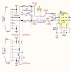
Below is an image of the circuit between the can transceiver and the can bus.

- Each node has two rj45 connections, to allow for the adding of more nodes
- We use UTP cat 5 cable for the connections, and we use one of the pairs for the CANL and CANH lines
- The power supply for each node is provided by the bus it self, using the other wires of the RJ45 connector
- Each node has a switch to turn on or off the bus termination resistor

I am suspitious ot the filtering and protection circuit that you see in the image, because we have an older version of these boards were the transceiver was connected directly to the bus(rj45 conectors) and we did not have this problem

One test I have already done is removing and short-circuiting the r11 and r16, and replacing the r29 with one of 120r, but there is no change in the nodes behaviour

thanks in advance for your help
canphysical.jpg
 
Last edited:

I am suspitious ot the filtering and protection circuit that you see in the image, because we have an older version of these boards were the transceiver was connected directly to the bus(rj45 conectors) and we did not have this problem

One test I have already done is removing and short-circuiting the r11 and r16, and replacing the r29 with one of 120r, but there is no change in the nodes behaviour

I am suspicious of the protection circuitry as well. The MCP2551 already offers protection against damage due to short-circuit conditions, Protection against high-voltage transients and high-noise immunity, so unless you are subjecting the devices to extraordinarily harsh conditions, I see no reason in its implementation.

At what speeds have you performed the tests?

Also can you post a diagram of how you are chaining the five or six devices together?

The standard CANbus termination should be 120Ω one at each end of the bus. For added emission reduction and EMC performance, split or biased split termination could be implemented.

BigDog
 

Hello,

Thanks for your reply, I started with 250kbps, works for three nodes, and lowered it to 125kbps, allowing me to have 5 nodes working without problems. Since se intended to have 60 nodes, this is a major problem for us

Regarding the nodes wiring, there is a utp cable connecting each two nodes from the "out" rj45 connector you can see in the diagram to the "out" rj45 of the next node. Tomorrow I will post a diagram to explain better, because now is 22pm in here :).

Best regards
 

How long are the intended cable lengths between each two nodes?

Also what type of environment will these devices be operating?

I'm still trying to understand, why all the protection circuitry that you predecessor designed and implemented?

BigDog
 

Hello,

The project is about a CAN sensor network, so the cable length between nodes may vary, from a few meters to some tens of meters.

The tipical environment were we will use the system is in data centers, however it can be applied to factories or other harsh environments, and it was because of that that the designer implemented the protection circuit.

I have been reading about CAN protection circuits and what I saw was similar to this one, but I also read somewhere that if these circuits are not very well dimensioned, they can cause problems on the bus, maybe that is the problem.

Best regards
 

Hello,

I have a project were several boards connect to each other using a CAN bus, however, I am having problems with the can physical layer.
If I add more than three nodes, they stop comunicating.

I discovered that if I add terminator resistors in each node, lowering this way bus impedance, they restart comunication but this should not be necessary. Also, the signal gets attenuated along the bus.
I also discovered that if I lower the bus speed, I can add two more nodes without having problems.

The hardware was not designed by me, but now I have to solve this problem, so I ask for your help

Below is an image of the circuit between the can transceiver and the can bus.

- Each node has two rj45 connections, to allow for the adding of more nodes
- We use UTP cat 5 cable for the connections, and we use one of the pairs for the CANL and CANH lines
- The power supply for each node is provided by the bus it self, using the other wires of the RJ45 connector
- Each node has a switch to turn on or off the bus termination resistor

I am suspitious ot the filtering and protection circuit that you see in the image, because we have an older version of these boards were the transceiver was connected directly to the bus(rj45 conectors) and we did not have this problem

One test I have already done is removing and short-circuiting the r11 and r16, and replacing the r29 with one of 120r, but there is no change in the nodes behaviour

thanks in advance for your help

View attachment 66643

Do you know you only need two terminated nodes not all of them terminated in the CAN bus?
 

Hello eziggurat, yes I now that, thank you
 

Hello,

I managed to contact the previous electronic designer, he told me that he uses this design with sucess in a network of 25 ndes, but at a speed of 25Kbps.
Probably it can all be solved with a component values change.
Anyway I am on the process of removing all the protection circuit to test the bus without it.
 

I've carefully reviewed the protection circuitry in your design.

One major drawback of using a Common Mode Choke is the possibility of oscillations due to unbalanced parasitic and component values.

You might try removing R11, R16 and L1, then replacing R29 with a split termination of two matched precision 60Ω resistors, there maybe a split termination package available.

Another option is the use of STP rather than UTP.

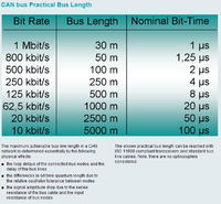
One thing to keep in mind is the CANbus speed ratings vs cable length:


Also are you chaining the nodes together by taking a cable from the output port of one node to the input port of the next node, with the two end nodes terminated by activating S1?

BigDog
 

Hello,

Thank you for our time.
Currently I ahave already done:
- removed R11 and R16;
- replaced r30 with a 120ohm one;
- removed r20 and connected pin RS of the transceiver directly to ground, because with this resistor the transceiver was working in slope control mode and not in Hi-speed mode.

All this improved a little bit the reliability of the bus, and I managed to have 6 nodes working with no errors as 125kbps.

I am also considering lowering the bus speed to something like 50kbps, but for now I will remove the L1 as you sugested and then add a split termination.

The chaining of the nodes is exactly as you described, they are chained together by taking a cable from the output port of one node to the input port of the next node, with the two end nodes terminated by activating S1.

I will keep you posted of the progress

regards

Luis Lima
 

Status
Not open for further replies.

Part and Inventory Search

Welcome to EDABoard.com

Sponsor

Back
Top