Welcome to our site! EDAboard.com is an international Electronics Discussion Forum focused on EDA software, circuits, schematics, books, theory, papers, asic, pld, 8051, DSP, Network, RF, Analog Design, PCB, Service Manuals... and a whole lot more! To participate you need to register. Registration is free. Click here to register now.
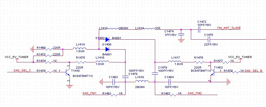
This is an antenna selection circuit.When you apply +5VDC SAD_SEL_B or SAD_SEL_C, either SAD_FM1 or SAD_FM2 is connected FM_ANT_SLAVE via PIN Diodes BA891.
Thank you for your reply.But I still have some questions:
1、What are the function of the inductors L1418,L1414,L1416 ?
2、Whether the diode and transistor will influence the receivetion of frequency,and how to select them?
3、If I use a similar circuit to design a FM/AM circuit ,how to select the value of the inductors and capacitors?
4、how to calculate the frequencey response of the circuit? Whether simulation with the multisim is right or not?
I have doubts about L1418, it is so small (180 Ohms at 100 MHz), that this one may have some other function. There is still some coupling between the two antenna inputs. When it only has a choke function, one could leave it out. Maybe they switch both diodes also to get a third diversity path.
An AM whip antenna behaves very different from an FM whip or on-glass antenna. Just scaling the capacitors and inductors with a factor of about 100MHz/600kHz may give unexpected results, but can be used as a starting point.
The band switching diode may be a problem. It is intended for VHF operation, the carrier lifetime may be too short for AM band operation. When the carrier life time is too short, you may get intermodulation products from the band switching diode. Maybe others have experience with this diode at lower frequencies.
When this circuit belongs to a diversity receiver, using it for AM has no real advantage as the antennas are too close together to have any benefit from diversity. Just selecting (one time) the best antenna will be OK.
Hello to all.
Actually,there is a third diversity path through antenna,the circuit and value are similar to SAD_FM1 and SAD_FM2.
I have doubts about whether there is a simple or better diversity receive circuit for radio.Can anybody recommend one?
Actually I have little knowledge about the diversity receive.Thank you very much for your reply
FM diversity makes an tremendous difference especially for FM car radios, where there is enough spacing between antennas.
More than 2 diversity antennas for a broadcast receiver I think is not worth. Sometimes there is a third antenna for the DAB receiver.
To vfone,
Actually I want to design a diversity receive circuit for a car radio.From your reply I think you are very experienced with such problem,Could you help me to solve the problem or recommend some materials?Thank you very much!
Actually you didn't say very clear what you don't understand, or what do you want to know more than this.
If you want a diversity switch, you already have it, you posted before.
If you want explanation how it works, above answers already did this.
hello,
Because my English is not very well,maybe I didn't express myself well.What I want to know is whether there is a more simple or better diversity receive circuit for car radio than I've post and how to design a good receive circuit for car radio to improve the sensitivity?If have the theory calculation will be better understand.
The diversity switch you posted is one of the simplest (and probably one of the best).
The only way as a diversity switch can improve sensitivity is to have the lowest insertion loss possible.
Put in a simulator, tune the components part of the filter for best performances having the right impedances at all ports, and that's it.
This site uses cookies to help personalise content, tailor your experience and to keep you logged in if you register.
By continuing to use this site, you are consenting to our use of cookies.