Continue to Site

Welcome to EDAboard.com

Welcome to our site! EDAboard.com is an international Electronics Discussion Forum focused on EDA software, circuits, schematics, books, theory, papers, asic, pld, 8051, DSP, Network, RF, Analog Design, PCB, Service Manuals... and a whole lot more! To participate you need to register. Registration is free. Click here to register now.

Calculation of Rin,out of audio filter

Status
Not open for further replies.
Rinput is infinite. Routput is infinite. If you are asking for IMPEDANCE, that's different. What's your frequency?
 
Assuming the input and output capacitors have negligible impedance at the filter frequency of interest then the output impedance is basically the op amp output resistance (as defined in the data sheet) divided by the loop gain (open loop gain minus the closed-loop gain) at the frequency of interest. The exact input impedance is a complex function of the input resistors and capacitors plus the feedback through C1. It's most easily determined using a Spice simulator.
 
The signal source of the Sallen-Key lowpass filter must be much lower than the input impedance of the circuit. Frequently the very low output impedance of an opamp drives it.
 
Hi and many thanks for your reply! I will give more information about my question on the schematic.

So the frequency bandwidth is DC to 17khz (audio)! Before this filter there is a double balanced ring diode mixer that downconvert a signal of 30MHz to a baseband DC to 17khz. The mixer's output (ideally) is 50ohm.

RF front....---Mixer-----Active Filter--Demodulator (DSP). I want to calculate the total gain of the stages of receiver but in the filter i don't know the Zinput and Zoutput to convert the voltage gain=20log(Vout/Vin) to power gain. I need to know what is the Zout and Zin. After the Active filter there is a DSP kit i think it's Zinput is about 10k maybe not sure...
Rinput is infinite. Routput is infinite. If you are asking for IMPEDANCE, that's different. What's your frequency?

- - - Updated - - -

Assuming the input and output capacitors have negligible impedance at the filter frequency of interest then the output impedance is basically the op amp output resistance (as defined in the data sheet) divided by the loop gain (open loop gain minus the closed-loop gain) at the frequency of interest. The exact input impedance is a complex function of the input resistors and capacitors plus the feedback through C1. It's most easily determined using a Spice simulator.


Hi and many thanks for your reply! I will give more information about my question on the schematic.

So the frequency bandwidth is DC to 17khz (audio)! Before this filter there is a double balanced ring diode mixer that downconvert a signal of 30MHz to a baseband DC to 17khz. The mixer's output (ideally) is 50ohm.

RF front....---Mixer-----Active Filter--Demodulator (DSP). I want to calculate the total gain of the stages of receiver but in the filter i don't know the Zinput and Zoutput to convert the voltage gain=20log(Vout/Vin) to power gain. I need to know what is the Zout and Zin. After the Active filter there is a DSP kit i think it's Zinput is about 10k maybe not sure...
 

The Sallen-Key lowpass filter has a voltage gain of 1 (like a piece of wire) at frequencies below its cutoff frequency. Its power gain does not matter.
The amplifier following the filter opamp has a voltage gain of (I can't read the tiny pastel sideways resistor values).
 
The Sallen-Key lowpass filter has a voltage gain of 1 (like a piece of wire) at frequencies below its cutoff frequency. Its power gain does not matter.
The amplifier following the filter opamp has a voltage gain of (I can't read the tiny pastel sideways resistor values).

Yes the Sallen-key is a unity gain amp Voltage Gain=1. About the Amplifier Stage there is a jumper of 2 option. First option's Gain is =R11/R13=10K/3,3K=3 and Second OPTion's gain is VARIABLE ( i have a potensiometer). So, let's say that is Gain=3. Reject the potensiometer. Maybe i can use KCL to find my Zin?
what can i do with the capasitors. they have Zc=1/jωC ...How can i add this with the Resistors? I am a begginer sorry about that

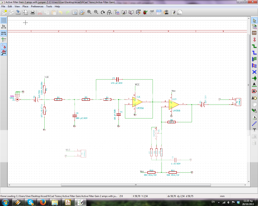
this is exactly the circuit : https://i1284.photobucket.com/albums/a578/fovos1/SISOFILTE_zps56bc4977.png
 

Why do you need to calculate Zin? Is this a school mathamatics exercise or is it a simple electronic circuit?
The filter circuit MUST be fed from a low impedance like the output of an opamp.

I still cannot read your tiny schematic with pastel sideways numbers on it and ads all over the page. Increase its contrast and post it HERE attached to your reply instead of posting it over at Photobucket.

- - - Updated - - -

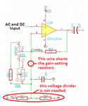
Your output opamp is WRONG:
 

Attachments

  • output opamp.png
    output opamp.png
    53.7 KB · Views: 105
Why do you need to calculate Zin? Is this a school mathamatics exercise or is it a simple electronic circuit?
The filter circuit MUST be fed from a low impedance like the output of an opamp.

I still cannot read your tiny schematic with pastel sideways numbers on it and ads all over the page. Increase its contrast and post it HERE attached to your reply instead of posting it over at Photobucket.

- - - Updated - - -

Your output opamp is WRONG:

SISO FILTE.png

okay now i believe it is ok?

I do an exercise with a RF Receiver.
Before this filter there is a double balanced ring diode mixer that downconvert a signal of 30MHz to a baseband. The mixer's output (ideally) is 50ohm.

RF front....---Mixer-----Active Filter--Demodulator (DSP). I want to calculate the total gain of the stages of receiver but in the filter i don't know the Zinput and Zoutput to convert the voltage gain=20log(Vout/Vin) to power gain. I need to know what is the Zout and Zin. After the Active filter there is a DSP kit i think it's Zinput is about 10k maybe not sure...

Why this voltage divider is wrong? According to **broken link removed**

at page 6 . non-inverting with single supply and page 26. sallen-key low pass with single supply i did that.
 

Before this filter there is a double balanced ring diode mixer that downconvert a signal of 30MHz to a baseband. The mixer's output (ideally) is 50ohm.
Then the low impedance mixer can directly drive this filter.

i don't know the Zinput and Zoutput to convert the voltage gain=20log(Vout/Vin) to power gain. I need to know what is the Zout and Zin.
The power gain has nothing to do with Zinput and Zoutput. The output power is Vout (from the opamp) squared/Rload. But there is no load.

Why this voltage divider is wrong?
Shame on Texas Instruments and shame on Cornell Edu for copying it. It is very wrong. See my corrections to it:
 

Attachments

  • opamp biasing.png
    opamp biasing.png
    14.6 KB · Views: 131
Then the low impedance mixer can directly drive this filter.

Yes exactly!

The power gain has nothing to do with Zinput and Zoutput. The output power is Vout (from the opamp) squared/Rload. But there is no load.

I am confused now. I want to do a cascade power gain... Lna (Zin=50,15dB,Zout=50) + filter(Zin=50,-3dB,Zout=50) +mixer (Zin=50,-8dB,Zou=50)+active filter(Zin=?,voltage gain 20dB,Zout=?)

to convert is to power gain is 20log(Vout/Vin)=20log(PoutZout/PinZin)^(1/2). that's why i want to do. why you say that power gain has nothing to do with Zinput and Zoutput?

Thanks for your help!
 

Power gain is normally used for RF fixed impedance lines which are typically 50 ohms. The op amp is operating at low frequency with a relatively high input and output load impedance. So you use voltage gain, not power gain, for the filter. Voltage gain is typically used for low frequency circuits. Calculating power gain for such a circuit makes no sense.
 
  • Like
Reactions: FvM

    FvM

    Points: 2
    Helpful Answer Positive Rating
Power gain is normally used for RF fixed impedance lines which are typically 50 ohms. The op amp is operating at low frequency with a relatively high input and output load impedance. So you use voltage gain, not power gain, for the filter. Voltage gain is typically used for low frequency circuits. Calculating power gain for such a circuit makes no sense.

Yes i understand what are you saying.But when you have a receiver chain you want to calculate the Power Gain of total chain. It is very practical. Please, take a loo here : enter in google "Receiver Architectures - Springer" it is a pdf 44 pages with Title Chapter 2 Receiver Architectures. Go on chapter 2.6 page 37 to 39 and you will understand what i am saying.

Is it so difficult to do that? My problem is that Capasitor's Impedance is Reactance . Zc=1/j2πfC...for example if i calculate for maximum freq=20Khz, first Capasitor=C=10^-6 Farads. So Zc=8/j. Then making KVL i will do finally Zin=Re+jX. The same at ouput. So the end i will have a Zout/Zin which is a complex number. :( i don't want something like this
 

But when you have a receiver chain you want to calculate the Power Gain of total chain.
It definitely makes no sense in this place, because there's no impedance matching involved.

So the end i will have a Zout/Zin which is a complex number. :( i don't want something like this
But it is. Fortunately it's meaningless regarding receiver performance.
(By the way, you can calculate a power transmission factor for complex loads, too)
 
So swamp the input with a resistor.....
However, your filter design is going to be all kinds of noisy (resistor thermal noise), as it has 15K in series with the input which sets the minimum impedance it presents to the mixer, get that down to something more reasonable.

Your diode ring mixers IMD performance will be strongly influenced by its terminating impedance anyway, so you need to do something about that gross mismatch for both noise and intercept reasons.
If I was designing a simple rx like this I would probably follow the mixer with a diplexer going over as low as I could find suitable magnetics for (maybe a Mhz or so), with the high pass leg terminated into a 50 ohm resistor. This takes care of the termination at high frequency, and the low frequency leg feeding a common base amplifier to isolate the mixer from the following filter (And to transform the impedances).

I would also suggest that MFB filters are usually better behaved then sallen & key in this sort of application.

I recommend "Experimental methods in RF design" for your reading pleasure.

HTH.

Regards, Dan.
 
It definitely makes no sense in this place, because there's no impedance matching involved.
I undertand what you are telling to me..but. If i want to write down "the Total Gain of my Receiver".what can i do for this? Please, enter in google "Receiver Architectures - Springer" it is a pdf 44 pages with Title Chapter 2 Receiver Architectures. Go on chapter 2.6 page 37 to 39.


How i can calculate a power transmission factor? with Zin and Zout?

Regards,

- - - Updated - - -

So swamp the input with a resistor.....
However, your filter design is going to be all kinds of noisy (resistor thermal noise), as it has 15K in series with the input which sets the minimum impedance it presents to the mixer, get that down to something more reasonable.

Your diode ring mixers IMD performance will be strongly influenced by its terminating impedance anyway, so you need to do something about that gross mismatch for both noise and intercept reasons.
If I was designing a simple rx like this I would probably follow the mixer with a diplexer going over as low as I could find suitable magnetics for (maybe a Mhz or so), with the high pass leg terminated into a 50 ohm resistor. This takes care of the termination at high frequency, and the low frequency leg feeding a common base amplifier to isolate the mixer from the following filter (And to transform the impedances).

I would also suggest that MFB filters are usually better behaved then sallen & key in this sort of application.

I recommend "Experimental methods in RF design" for your reading pleasure.

HTH.

Regards, Dan.

Dear Dan, many thanks for your help. Many people have recommended me this book. I am a beginner so, is it for my level?

Also, i don't understand why you tell me to swamp the capasitor with a resistor. what value resistor for that capacitor?is it any technique?

About poor impedance matching with mixer's output i agree.But i didn't know what to do. This solution with diplexer seems cool but i don't have any idea what is this stuff. I think is too progressive for my level! Thanks by the way
 

If I was designing a simple rx like this I would probably follow the mixer with a diplexer going over as low as I could find suitable magnetics for (maybe a Mhz or so), with the high pass leg terminated into a 50 ohm resistor. This takes care of the termination at high frequency, and the low frequency leg feeding a common base amplifier to isolate the mixer from the following filter (And to transform the impedances).
I guess it won't be needed. We would firstly ask if the AF output needs termination at all. Secondly if a low impedance termination has any AF SNR impact. Only if the answer is true in both cases, the effort actually pays.
 

Ok, at high frequency the lowest impedance possibly seen at the filter input is trivially R1||R5||R2, so say somewhere about 12K or so at a guess, it rises towards DC as the reactance of the input coupling cap rises and the various filter capacitors become more significant reaching infinity at DC due to the input blocking cap.

Now you could match this by using a transformer to step the 50 ohms from the mixer up to 12K, but that is one hell of a ratio and even if you do this you still have a problem with the behaviour in the passband where the impedance is both high and complex.

A common base stage out of the mixer will serve to isolate the mixer from the filter even if you forgo the diplexer, which will help, but you still want to re design that filter to be better behaved impedance wise. Go for 10 times the value on the caps and 1/10th the values on the resistors and your noise will come down by a useful amount while the input match will become much better (Stll about 20:1 or so, but better), a common base stage with the collector load being a transformer into the filter would be how I would be thinking at that point and is about as simple as it gets.

And yes, EMRFD is the book you want, get thee to the library (Also ARRL Handbook, Radcom Handbook, Terman).

73, Dan.
 
Now you could match this by using a transformer to step the 50 ohms from the mixer up to 12K
a common base stage with the collector load being a transformer into the filter would be how I would be thinking at that point and is about as simple as it gets.

Sounds to me like two solutions for a non-existing problem...
 

The mixer termination is not just about the AF, it also serves to reduce reflected power back into the mixer all the way across the band which helps massively with the intercept point and also helps to reduce the effect of LO spurs, diode ring mixers really do need all ports to be terminated relatively well if they are to give good performance.

In fact it is often worth putting a 3dB pad between the LO and the mixer to improve the broadband termination of that port as well, the extra 6dB return loss (at the cost of 3dB more drive power) is worth it in many cases.

Remember that the diodes will produce all sorts of harmonics which you had better absorb somewhere or you will get all kinds of spurs and birdies.

Don't get too hung up on power gain calculations, once you are down to audio (and away from the mixer) you are into a world that uses voltage rather then power transfer in most cases, so while you could write something like 0.1uW input for 1W output into 8 ohms at maximum gain (= 70dB power gain) it is not all that useful.

73, Dan.
 
  • Like
Reactions: FvM

    FvM

    Points: 2
    Helpful Answer Positive Rating
Status
Not open for further replies.

Similar threads

Part and Inventory Search

Welcome to EDABoard.com

Sponsor

Back
Top