Continue to Site

Welcome to EDAboard.com

Welcome to our site! EDAboard.com is an international Electronics Discussion Forum focused on EDA software, circuits, schematics, books, theory, papers, asic, pld, 8051, DSP, Network, RF, Analog Design, PCB, Service Manuals... and a whole lot more! To participate you need to register. Registration is free. Click here to register now.

Calculating SpO2 in pulse oximetre, 16F877A PIC

Status
Not open for further replies.
@ Fragrance :

Thanks for the docs , can you tell me why using +12 , -12 in the circuit ?!
cant we just use +5 , GND instead ?!

yes you must used dual supply voltage for rail to rail operation and better signal conditioning

regards
Fragrance
 
Hello everybody and thank you Fragrance for helping us.

Now, after 2 weaks of struggle with this project, I have to tell you that I lost hope.

From my point of view, there are major flaws in this project.

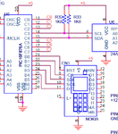
How can you power up your nokia 5110 display with 5 V ? In the schematic, there is not clear how to connect the pins from the display.

The display have 9 pins: 1-VDD 2-SCLK 3-SI 4-D/C 5-/CS 6-OSC 7-GND 8-VOUT 9-RES. In the schematic, you can connect 1,2,3,4,5,7 and 9 and 6-OSC and 8-VOUT are not connected. Also, there are a couple of pins which are not connected(10 actually).

Again, nokia 5110 display needs 3.3 V to function, not 5 V. Yes there are reports on the net, that this display can take 5 V but no real evidence. Anyway, I have tryed with 5 V and nothing.

Now, about the code. I was able to compile it. But my 16f876A was only able to light the leds.

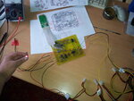
20120420_093020.jpg

I hope there is some one here who really made it !

Thank you !
 
Hello everybody and thank you Fragrance for helping us.

Now, after 2 weaks of struggle with this project, I have to tell you that I lost hope.

From my point of view, there are major flaws in this project.

How can you power up your nokia 5110 display with 5 V ? In the schematic, there is not clear how to connect the pins from the display.

The display have 9 pins: 1-VDD 2-SCLK 3-SI 4-D/C 5-/CS 6-OSC 7-GND 8-VOUT 9-RES. In the schematic, you can connect 1,2,3,4,5,7 and 9 and 6-OSC and 8-VOUT are not connected. Also, there are a couple of pins which are not connected(10 actually).

Again, nokia 5110 display needs 3.3 V to function, not 5 V. Yes there are reports on the net, that this display can take 5 V but no real evidence. Anyway, I have tryed with 5 V and nothing.

Now, about the code. I was able to compile it. But my 16f876A was only able to light the leds.

View attachment 72868

I hope there is some one here who really made it !

Thank you !

do not lost hope i will check and come to you again

regards
Fragrance
 
  • Like
Reactions: Jongs

    Jongs

    Points: 2
    Helpful Answer Positive Rating
@Fragrance : thanks for answering my question

I'm trying to do the same circuit JONGS did , i found the same problem in the display pin configuration

@Jongs , have you test the signals in the Testing points ?! if they were right as the ones given in the schematic i think you are only having display problem then .
what do u think if we try to change the nokia LCD with normal LCD and print out the spo2 & Pulse rate on it ?!

anyone knows how to reach narccizzo ?!

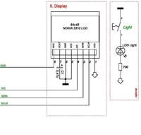
as there is no part list provided with original archive further not mentioned in the schematic what type of LCD is that and from which model of Nokia phone, the best way is that concern with LCD display data sheet, i have attach an image for Nokia LCD connection for reference purpose only as the attach image belong to 3310 LCD display, further i have attach an other design which i have made and working fine.

33_1334981988_thumb.jpg


**broken link removed** uploaded large file out side forum to save space on board

regards
Fragrance
 
  • Like
Reactions: Jongs

    Jongs

    Points: 2
    Helpful Answer Positive Rating
  • Like
Reactions: Jongs

    Jongs

    Points: 2
    Helpful Answer Positive Rating
The following is the datasheet for the PCD8544/Nokia 5110 display controller:

PCD8544 48x84 pixels matrix LCD controller/driver

A few tutorials and example projects using the Nokia 5110 LCD:

5110 Quick Start Tutorial

Arduino Example Philips PCD8544 (Nokia 3310) driver


BigDog

BigDog Thanks for sharing data sheet, to Lebronic you can make test run under Proteus just wire up CPU and LCD with setting switch and not setup rest hardware run simulation to see result and then used same hardware setting in real, i will share some other good Nokia LCD Proteus model by Monday

regards
Fragrance
 

Thanks Fellos
i think the best way is to change the display
i'm trying to do that , using 16x2 LCD display and modifying the code to make it working

the problem i'm facing when using a simple code to view two words (SPO2=,PPM=) (and some constant values ) in proteus it doesnt really show the two words and constant number ! dont know why but i'm using this 16x2 LCD connected to the port B (as NOKIA lcd display connected to the same port ),then i'm going to pass the Sao2 variable to the LCD method to write the exact number each time it calculated spo2

here's How i connect the LCD Display
DISPLAY (D1,D2,D3,D4,RS,Enable) = (B0,B1,B2,B3,B4,B5)
using flowcode i was able to make it working , i generate the hex file to implement it in proteus , but it doesnt show up
Ashampoo_Snap_2012.04.21_21h38m50s_002_.png

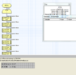
Here's on flowcode :
Ashampoo_Snap_2012.04.21_21h41m12s_003_.png

my first thoughts about the modification is like this
Ashampoo_Snap_2012.04.21_21h30m49s_001_.png
 
Last edited:
Thank you Fragrance and BigDog for helping us !

Unfortunately I'm stuck with this project and I've to find a solution regarding the nokia display.

I'm using a nokia 5110 phone with the display, not the display alone.

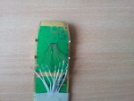
display.jpg

On the back of the display, as you can see there are 9 connection points:

1-VDD 2-SCLK 3-SI 4-D/C 5-/CS 6-OSC 7-GND 8-VOUT 9-RES

Our schematic from the project is this:

connections.png

I connect 1-VDD 2-SCLK 3-SI 4-D/C 5-/CS 7-GND 9-RES, but the problems are:

First, 1-VDD, as you can see, is at 5 V. From nokia display datasheet I can see that we need 3.3 V. How Narccizzo, the original author of this project made it ?

Second, what we do with the 6-OSC and 8-VOUT ? They are left open ?

Thank you Fragrance and BigDog for your kind help !
 
  • Like
Reactions: vik424

    vik424

    Points: 2
    Helpful Answer Positive Rating
hi gud ppl,
i m sorry to take you backward.I got a problem just at the begining,wanna go from designing the probe and i have the 2 led and the photodiode.I would like to use the 555 time as the frequency generator but dont know if i must use one or two for each led and if i m using two how will i sinchronize them to do not go at the sametime as they are 2 differnt ic.
thx
leonel
 

@Jongs :

Voltage difference: 5.5v vs 3V

Both LCDs are designed to work with 3.3V, but due to an internal voltage clamp 5V can be used for SCLK, SDATA, REST, D/C and CS as long as a current limiting resistor (around 10k) is connected in series for each line. 3.3V should still be applied to VCC and the LED supply. I have tried using voltage dividers, which did not work, perhaps due to the LCD varying internal resistance and current consumption.

With the above connections we can only write to the LCD but can't read back the LCD response because 3.3v is not high enough to register as logic '1' in the PIC. Luckily reading from the LCD is not required for basic operations; all that is needed is sufficient delay after each operation to make sure the LCD is ready for next command.

I have chosen the PIC16f88 simply because it's available in my junk box. However, as the 16f88 does not have dedicated hardware SPI required by the LCD modules, bit-banging has to be used to simulate SPI. Although this usually means complicated code and lower throughput, it does not matter as all I wanted is to get the LCD to display something useful ;)

@leonel : regarding the sensor , you can use two LED (infra & RED ) with the photodiode directly without the need of 555 (if you are using narracoz design )
(look on the photo provided by JONGS how he attach them directly to desired points)
other solution , which i'm doing , is to use a nellcur Sensor you will have 9 Pin Connector , you can connect 5-9 to photodiode , and 3-4 to AD620 .
 

the pic put by jongs only showing the lcd and pic. how do you want me to generate the pulse of frequency on the leds without the 555 timer?
can you send me the narracoz design plz i dont have it
thx
 

hi
sorry i dont understand correctly that cicuit,
my concern is at the bigining.What do u use to pulse the leds?
 

wow thx very much for the help.
got some more question
can i replace the ic ad620 with opa381? as it's une as trans-impedance amplifier or is there any raison of usinf exactly that one?
and can i use LM741 instead of TL084?
What is the name of a IC that i can use as buffer?
on the circuit that you sent me : thetion C0 to C7 wer are they connected to?
I can see C1 is connected to R24, but all the other I dont knw wer to connect them
as well as the circuit having pin 8 and pin9 wat is it for and wer doi connect it? to
plz help
please help me once again
 

C0-C7 is connected from the Resistors to the port C on the pic
and then from Resistors to photo diode of the sensor
Pin 8 , 9 it's the bypass Capacitor for LCD,PIC, EPROM
 

Thanks Fellos
i think the best way is to change the display
i'm trying to do that , using 16x2 LCD display and modifying the code to make it working

the problem i'm facing when using a simple code to view two words (SPO2=,PPM=) (and some constant values ) in proteus it doesnt really show the two words and constant number ! dont know why but i'm using this 16x2 LCD connected to the port B (as NOKIA lcd display connected to the same port ),then i'm going to pass the Sao2 variable to the LCD method to write the exact number each time it calculated spo2

here's How i connect the LCD Display
DISPLAY (D1,D2,D3,D4,RS,Enable) = (B0,B1,B2,B3,B4,B5)
using flowcode i was able to make it working , i generate the hex file to implement it in proteus , but it doesnt show up
View attachment 72962

Here's on flowcode :
View attachment 72961

my first thoughts about the modification is like this
View attachment 72960

you made wrong connection for LCD to make setup for test, make connection like this used D4,D5,D6,D7 for data input and ground the D0,D1,D2,D3 also ground the pin 5 of LCD
 
  • Like
Reactions: lebronic

    lebronic

    Points: 2
    Helpful Answer Positive Rating
    V

    Points: 2
    Helpful Answer Positive Rating
@Frag
Yes Sir this was helpful i could show up the two values


Now i have the C code for showing the values , and the main c (with the Nokia LCD)
we need to combine both to get the ability to show the real values
 

    V

    Points: 2
    Helpful Answer Positive Rating
hi
sorry if i m asking too much but why are we powering the 2 leds with 3 output of the pic(for each led).
knowing that a output give 5V .why are we using 3 output for each?
and the small circuit with transistor i believe is to create a sort of constant current or what is the use of it? if i m right why is it only on the pin 3 not pin 4? those two pin are for the leds.
finally the pin 8 and 9 are just ground line right?
thx for your support
leonel
 

Status
Not open for further replies.

Similar threads

Part and Inventory Search

Welcome to EDABoard.com

Sponsor

Back
Top