Continue to Site

Welcome to EDAboard.com

Welcome to our site! EDAboard.com is an international Electronics Discussion Forum focused on EDA software, circuits, schematics, books, theory, papers, asic, pld, 8051, DSP, Network, RF, Analog Design, PCB, Service Manuals... and a whole lot more! To participate you need to register. Registration is free. Click here to register now.

[SOLVED] Calculate values in an amplifier

Status
Not open for further replies.
Yes, indeed.

If you set up the equations for a Matlab solution, it will be a trivial matter to change the gm values for the FETs and solve again.

And, tell me what software you use to make your model drawings.
 

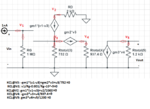
I think I might need a little help with getting the equations right with the nodal analysis first, im working on them right now.

Well, the software for drawing the circuits is just something I googled which was easy to learn, CircuitLab

- - - Updated - - -

The first attempt at the nodal analysis have been made but with a few question marks!
Don't know what to do with the "interruption(but not interruption)" between node 1 and 2.
And I don't know what to do with the current going out of the circuit farthest to the right.

alltogethernodal.png
 

You don't need to deal with any current leaving v1 to the right, or current leaving v3 to the left, or current leaving v5 to the right, because there is no current in those cases. So don't show current arrows in those directions. Wires that don't connect to anything don't carry a current so get rid of expressions for those "currents".

At v5 we only need to know the voltage with no additional load. The load RL is included in your equivalent resistor.

You should apply a stimulus at the input. We only need to know the voltage gain v5/v1, so we can use any stimulus we like. I would apply a current source to the input such that it causes a .001 volt drop in Rg; that would be a current of 1/1000000000 amp. This gives you an equation at v1 which is simply the sum of that current stimulus and the current in Rg.

Your first equation should be:
KCL@v1: v1/Rg - .001/Rg = 0

The rest of your "equations" aren't equations; you need to have "=0" on the right side of each of them.
 
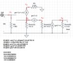
I have corrected the schematics, and applied a 1nA current source to the input.

I'll set these equations up in Matlab now, to solve for all the V*s

alltogethernodalmedcurrensource.png

---------------------------------------

alltogethernodalmedcurrensource.png

So the voltage gain V5/V1=-0.0380364V/0.002V=-19.0182V/V

So shouldnt that give us 0.001*-19.0182=-0.0190182V if the input is sin(1000t)=1mV?
 
Last edited:

Your first equation should be:
KCL@v1: v1/Rg - .001/Rg = 0

But somehow you have:

KCL@v1: v1/Rg - .001/Rg - 10^-9 = 0

You have the applied input current in the equation twice. Get rid of the part in red.

You will still get the same overall gain, but the voltages at the various nodes will be correct.

The output voltage will be -0.0190182 sin(10³t) V

It's interesting to note the gains of the individual stages as v3/v1, v4/v3 and v5/v4.

By solving again with a different value of RD we can see if RD has any effect on the overall gain. Even though it doesn't, its presence will lessen the dynamic range of the first stage. Large input signals would be clipped sooner than if it's absent.

You can also change rpi to 1.5kΩ to match the problem statement (gm3 is again β/rpi). You'll have to take that up with your instructor.

I will be interested to learn if you have the correct answer for such a complex problem.
 

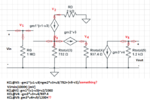
Alright! So just to be as thorough as possible for future reader, I'll post the correct schematics and the equations below.

alltogethernodalmedcurrensource.png

gm1=0.0007640S
gm2=0.00342857S
gm3=0.0356436S

KCL@V1: v1/1000,000-0.001/1000,000=0
KCL@V2: gm1*(v1-v3)+v2/2000=0
KCL@V3: -gm1*(v1-v3)+gm2*v3+v3/752=0
KCL@V4: -gm2*v3+v4/937.4=0
KCL@V5: gm3*v4+v5/1200=0

=>

V1=0.001V
V2=-0.00131661
V3=0.000138347V
V4=0.000444639V
V5=-0.0190182V

Voltage gain: V5/V1=-0.0190182/0.001=-19.0182V/V

With input of 1mV, the output voltage is 0.001*-19.0182=-0.0190182V


-----------------------------

With gm1 and gm2 set as 4mS and rpi=1500Ω

β/rpi => 100/1500=0.0666667S = gm3.

gm1=0.004S
gm2=0.004S
gm3=0.0666667S

=>

V1=0.001V
V2=-0.00457013V
V3=0.000428734V
V4=0.00160758V
V5=-0.128606

Voltage gain: V5/V1=-0.128606/0.001=-128.606V/V

With input of 1mV, the output voltage is 0.001*-128.606=-0.128606V
 

V1=0.001V
V2=-0.00457013V
V3=0.000428734V
V4=0.00160758V
V5=-0.128606

The values for v4 and v5 are incorrect. In equation KCL@V4: -gm2*v3+v4/937.4=0 you have a constant equal to 937.4

That constant is derived from:

1/(1/R4 + 1/R5 + 1/R6 + 1/rpi)

But when you change rpi to 1500, you must change that constant to 726.199 before you re-solve the system.

The correct values are:

v4 = .00124538
v5 = -0.0996305

This error is why you shouldn't simplify like you did in post #38. If you later decide to vary a value (such as rpi), the unsimplified equations will still give the correct values, but if you simplify, you may forget to go back and re-calculate the simplified values.

Since Matlab is doing all the arithmetic, there's not much reason to simplify the equations which Matlab is solving.
 
Status
Not open for further replies.

Part and Inventory Search

Welcome to EDABoard.com

Sponsor

Back
Top