Continue to Site

Welcome to EDAboard.com

Welcome to our site! EDAboard.com is an international Electronics Discussion Forum focused on EDA software, circuits, schematics, books, theory, papers, asic, pld, 8051, DSP, Network, RF, Analog Design, PCB, Service Manuals... and a whole lot more! To participate you need to register. Registration is free. Click here to register now.

Building circuit to supply a PCB with -5V, having +12V and ground available

Status
Not open for further replies.

smeggbrain

Newbie level 2
Joined
Apr 8, 2013
Messages
2
Helped
0
Reputation
0
Reaction score
0
Trophy points
1,281
Activity points
1,298
Building circuit to supply a PCB with -5V, having +5V and +12V and ground available

Hi everyone!

My first post here, I hope this gets into the right place. My task is a follows:

I have an existing power supply connected to the AC grid providing the following:
+12 V (2 A)
+5 V (12 A)
and +3.3 V (12 A),

all DC Voltage. This is a power supply for an arcade PCB board (game).
Now I have another game which needs -5V DC as well. It needs to use the same ground as the previously mentioned voltages of course.

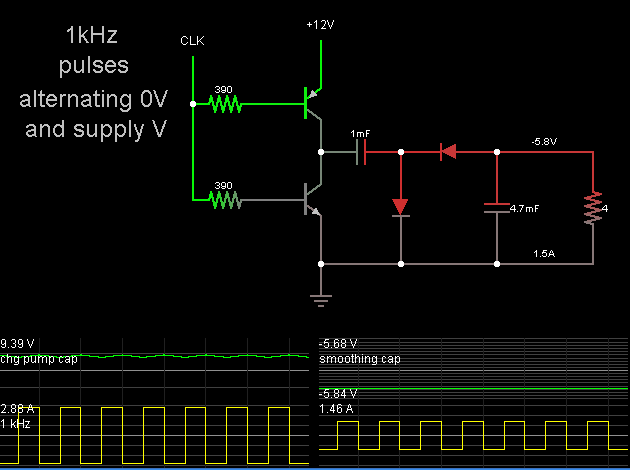
So my plan is to build a -5V terminal, that is able to deliver up to 1.5 A (usually less), using the other DC voltages a supply somehow.

What would be a good way to build this? Any suggestions for a simple circuit?

Thanks,
-smeggbrain
 

You are looking for a "negative boost converter" I expect.
But my advice to you, if you're interested in the result
more than the adventure, is to find a PC ATX power
supply which can be had for free or dirt cheap and
give you all of the voltages you mention with substantial
excess capacity.
 

There are lots and lots and lots and lots and lots and lots and lots and lots and lots and lots and lots and lots and lots and lots and lots and lots and lots of resources on the web about switching regulators. Google is your friend, just do a search of voltage inverter ics.

Here's one of many places to look.

https://www.ti.com/lsds/ti/analog/powermanagement/power_portal.page

Also look at maxim-ic.com, linear.com
 

Thanks a lot for the advice! It was really helpful.
I think the problem with google is filtering the results, but I have a few very good leads now, which I needed :smile:
 

If you have more current then you need on +5V rail you can change direction of few electrons and make -5V with inverting designs. :smile:
 

This is a simple method to obtain a negative supply.


The PNP-NPN half-bridge drives a negative charge-pump peak detector.

The clock can be any convenient pulse generator. Its volt level must go high enough to turn off the PNP transistor.

You can either add a negative voltage regulator, or you can adjust values to obtain -5V at your load.

- - - Updated - - -

This is a simple method to obtain a negative supply.


The PNP-NPN half-bridge drives a negative charge-pump peak detector.

The clock can be any convenient pulse generator. Its volt level must go high enough to turn off the PNP transistor.

You can either add a negative voltage regulator, or you can adjust values to obtain -5V at your load.
 
  • Like
Reactions: tpetar

    tpetar

    Points: 2
    Helpful Answer Positive Rating
Status
Not open for further replies.

Part and Inventory Search

Welcome to EDABoard.com

Sponsor

Back
Top