Continue to Site

Welcome to EDAboard.com

Welcome to our site! EDAboard.com is an international Electronics Discussion Forum focused on EDA software, circuits, schematics, books, theory, papers, asic, pld, 8051, DSP, Network, RF, Analog Design, PCB, Service Manuals... and a whole lot more! To participate you need to register. Registration is free. Click here to register now.

[SOLVED] Buck Converter for 3 stage battery charger

Status
Not open for further replies.

emaniac

Member level 1
Joined
Feb 24, 2014
Messages
35
Helped
0
Reputation
0
Reaction score
0
Trophy points
6
Activity points
303
Hi

I'm working on Buck converter, using IR2110 and now planning to take it to next stage (interleaved Buck). Controller is PIC16F877A.

I would like to know if it's possible to generate Interleaved PWM with PIC16F877A(Not that I know of) or should i upgrade my controller?

If Yes, Please suggest me a Controller.


Can anyone explain me how the Constant Current(CC) or BULK Stage Work?

How to set the Constant Current (incase it is a 20A charger controller) in Bulk Stage?

How about the Voltage Setpoint of the "controller" in BUlk Stage?

I'm not expecting any exact codes or circuit Diagram. Just Ideas andexplanations.


Thank you
 

I would like to know if it's possible to generate Interleaved PWM with PIC16F877A(Not that I know of) or should i upgrade my controller?

No, PIC16F877A is very perfect for your design because of its ADC pins


Can anyone explain me how the Constant Current(CC) or BULK Stage Work?

How to set the Constant Current (incase it is a 20A charger controller) in Bulk Stage?

Seeing the relationship between voltage and current in a BULK converter circuit
Vout = duty cycle * Vin
Iout = Iin * 2 at 50% duty cycle
How about the Voltage Setpoint of the "controller" in BUlk Stage?

The voltage setpoint can be done using a Feedback from the Vout through a voltage divider to the ADC pin of microcontroller to adjust the duty cycle of your period.
 

Hi
Thank you for the reply Pulsetronics.
I have difficulty understanding the battery charging operation with a 3 Stage Battery Charger.

For charging a 12V Battery,
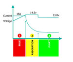
referring to the image

Battery_Stage.jpg

In Absorption stage or Constant Voltage Stage "the charger controller" maintains a voltage of 14.5V
In Float Stage the output Voltage of the Charger controller is lowered to 13.8V

and now to stage 1

1. In Bulk Stage what should be the output Voltage(in figures) of the charger controller?

2. From the fig. In constant current stage the current is 18A, How does the charger controller maintains 18A to the battery. what logic should be used by charger controller so it maintains 18A to the battery?

Please feel free to correct me if any of my understanding from the fig. is wrong.

Regards
 

You have to use an output current sensor (ACS714).

For stage 1: by reading the output current value with your PIC (ADC pin) you could increase/decrease the PWM ratio to keep that output current at a constant value (18 A). You don't have to worry about the output voltage as the battery internal resistance will self regulate it.

For stage 2, you have to read the output voltage and modify the PWM ratio accordingly to keep the output voltage constant (14.5 V). The output current will drop slowly (the battery internal resistance will increase durring charging).

For stage 3, you only have to watch for the output voltage, too (but for a lower value: 13.8V).
 

Status
Not open for further replies.

Similar threads

Part and Inventory Search

Welcome to EDABoard.com

Sponsor

Back
Top