Continue to Site

Welcome to EDAboard.com

Welcome to our site! EDAboard.com is an international Electronics Discussion Forum focused on EDA software, circuits, schematics, books, theory, papers, asic, pld, 8051, DSP, Network, RF, Analog Design, PCB, Service Manuals... and a whole lot more! To participate you need to register. Registration is free. Click here to register now.

Buck/Boost DC-DC Converter Operating in Discontinuous Conduction Mode

Status
Not open for further replies.

jegues

Member level 3
Joined
May 29, 2011
Messages
58
Helped
0
Reputation
0
Reaction score
0
Trophy points
1,286
Activity points
1,915
Hello all,

I'm having some trouble figuring out the average inductor current for the Boost Converter when operating in Discontinuous Conduction Mode.

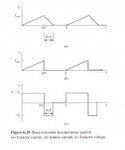
If we look at the analysis/waveforms for the Buck converter (see first figure attached) we can find the average inductor current as follows,

\[I_{L,BUCK} = \frac{\frac{1}{2}I_{max}DT + \frac{1}{2}I_{max}D_{1}T}{T} = \frac{1}{2}I_{max}(D + D_{1})\]

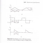
If I apply this same technique to the Boost converter waveforms (see second figure attached) and solve for the average inductor current I get,

\[I_{L,BOOST} = \frac{\frac{1}{2}I_{max}DT + \frac{1}{2}I_{max}D_{1}T}{T} = \frac{1}{2}I_{max}(D + D_{1})\]

but according to my text this result is incorrect. Why?

My textbook implies that,

\[I_{L,BOOST} = \frac{1}{2}I_{max}\]

which is simply the midpoint of the sloped portion of the inductor current, which is where we'd expect the average to be, but then it begs the question as to why the average inductor current for the Buck converter is,

\[I_{L,BUCK} = \frac{1}{2}I_{max}(D + D_{1}) \neq \frac{1}{2}I_{max}\]

What am I neglecting?
 

Attachments

  • Q-_0128_NEW.jpg
    Q-_0128_NEW.jpg
    168.6 KB · Views: 143
  • Q-_0130_NEW.jpg
    Q-_0130_NEW.jpg
    214.2 KB · Views: 127

Hi Jegues,

When the Buck or Boost Converter operating in DCM, the operating period T is not equal to D+D1, and the operating period T is not equal to 1, so I think that the calculation of the average current of the Boost Converter operating in DCM in your textbook may appear some mistakes. may be operating in CCM.

Attached below are the pages from my textbook for which I am concerned.

On page 245 we can calculate the average inductor current as follows,

\[I_{L} = \frac{1}{2}I_{max}(D+D_{1})\]

Now what I thought an equivalent expression for the diode current would be,

\[I_{D} = \frac{I_{L}D_{1}T}{T} = I_{L}D_{1}\]

Is this incorrect? If so, why?

It is clear from the graph of the diode current on page 245 that indeed,

\[I_{D} = \frac{\frac{1}{2}I_{max}D_{1}T}{T} = \frac{1}{2}I_{max}D_{1}\]

but instead of calculating the area of a triangle, I've always "stretched" that triangle into a rectangle since I know that the current flowing through the diode for that time frame (i.e. D1T) is the average inductor current. With this in mind, the area of my rectangle would be,

\[I_{D} = \frac{I_{L}D_{1}T}{T}\]

This is thought of stretching the area of said triangle into a equivalent rectangle has previously worked for me when doing the analysis for the Buck converter under discontinuous conduction mode. In particular, I wrote

\[I_{s} = I_{L}D\]

where Is is the source current.

Does the source of my confusion make sense? Can you see where I'm going wrong?
 

Attachments

  • Q-_0131_NEW.jpg
    Q-_0131_NEW.jpg
    607.7 KB · Views: 135
  • Q-_0132_NEW.jpg
    Q-_0132_NEW.jpg
    437.1 KB · Views: 139
Last edited:

I think "Is=ILD and ID=ILD1" is correct.

- - - Updated - - -

You can also use the simulation software to verify your calculation. For example, Pspise

- - - Updated - - -

modify: Pspice
 

I think "Is=ILD and ID=ILD1" is correct.

- - - Updated - - -

You can also use the simulation software to verify your calculation. For example, Pspise

- - - Updated - - -

modify: Pspice

I can't see any of your work if you are trying to post it.

Can you see where I'm getting confused? With my equation for ID and IL I would get,

\[I_{D} = \frac{1}{2}I_{max}(D+D_{1})D_{1}\]

Which obviously differs from what they have in the textbook.

Why?
 

Hi,Jegues,

for your information:

In CCM, the operating period T is equal to “D(Ton)+D1(Toff)” or 1.
In DCM, ”D(Ton)+D1(Toff)” is less than T or 1.

In Figure 6.22 (C) from page 245, we can figure out the average current of diode,

IDave=(ILmax×D1)/(2×T)
Where T is 1.

In figure 6.22(a),for the average current of inductor, we can calculated

ILave=ILmax×(D+D1)/(2×T)

For the average of the input source current,

Isave=(ILmax×D)/(2×T)


So, I think your calculation above is correct.

If operating in CCM, because T =D+D1=1, IDave=ILmax×(D+D1)×D1/(2×T) should is correct.
Where T is still 1.
 

If operating in CCM, because T =D+D1=1, IDave=ILmax×(D+D1)×D1/(2×T) should is correct.
Where T is still 1.

So if we are operating in CCM that expression will simplify down to,

\[I_{D} = \frac{1}{2}I_{max}D_{1}\]

Which is what the textbook has on the bottom of page 244.

BUT WE ARE NOT IN CCM RIGHT?!?

How can they possibly simplify it down to

\[I_{D} = I_{L}D_{1} = \frac{1}{2}I_{max}D_{1}\]

???

I would've expected,

\[I_{D} = I_{L}=D_{1} = \frac{1}{2}I_{max}(D+D_{1})D_{1}\]

Because D+D1 is not equal to 1, WE ARE NOT IN CCM!

Can you understand my confusion?
 

No matter in CCM or DCM or CRM , operating period “T” is always equal to 1. Therefore, in figure 6-22(c), The diode average current only with “D1” “ILmax” is concerned, or only with the area of a triangle is concerned,The textbook is correct

Idave=ILmax×D1/2

Do you understand ?
 

Status
Not open for further replies.

Similar threads

Part and Inventory Search

Welcome to EDABoard.com

Sponsor

Back
Top