Welcome to our site! EDAboard.com is an international Electronics Discussion Forum focused on EDA software, circuits, schematics, books, theory, papers, asic, pld, 8051, DSP, Network, RF, Analog Design, PCB, Service Manuals... and a whole lot more! To participate you need to register. Registration is free. Click here to register now.
The picture is just half of the information. Give us the link to where you found it.
We (you) need to read the context.
Currently we don't know whether it shows
* current
* voltage
* duty cycle
* anything else
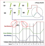
The slope is the di/dt = V/L where L is the coil inductance. V is the DC bus of the 3Phase brij.
Remember in a BLDC , you have the coil to coil commutation...and also, the high frequency current regulation commutation within that. Basically a 3 phase bridge is 3 step down buck converters, which control their output current.
This site uses cookies to help personalise content, tailor your experience and to keep you logged in if you register.
By continuing to use this site, you are consenting to our use of cookies.