lineofstars
Newbie level 4
Hi everyone.Well first of all I have to say that is amazing how this kind of communication unite us,despite of the distance,language,religion,politics,gender(man or woman)....etc.
I know things about computers repairing not only my own PC at hardware failure and software level inst-desinstall(OS),but also when a friend or friend of that friend ask help and Im in the right position to give it.
Despite that,in electronics im quite green,so for sure I will need all the brains around and all the possible patience that a person or human being can hold inside.
So I explain the facts, suddenly the TV start making a strange sound to the speakers,than there the sound has gone.The speakers I have checked them connecting to other device.The audio jack output also does not work because I have tested with an earphone.
The exact tv model and info are:
Blaupunkt TV,model # W23/173I-GB-FHBKUP-DE
Ref B23C173TCFHD
Product code BW23R173BFBKPE404
Serial Number BW23R173BFBKPE404-107426 00808
Motherboard serial t.msd309.28b
Photos link to see the motherboard:
https://plus.google.com/photos/1027...6079107625735817218&oid=102793503591974069148
https://plus.google.com/photos/1027...6079108071896586770&oid=102793503591974069148
https://plus.google.com/photos/1027...6079108387635073554&oid=102793503591974069148
https://plus.google.com/photos/1027...6079108753207936914&oid=102793503591974069148
https://plus.google.com/photos/1027...6079109117947711538&oid=102793503591974069148
https://plus.google.com/photos/1027...6079109475267788786&oid=102793503591974069148
https://plus.google.com/photos/1027...6079109887551514674&oid=102793503591974069148
https://plus.google.com/photos/1027...6079110207183580290&oid=102793503591974069148
https://plus.google.com/photos/1027...6079110569102090482&oid=102793503591974069148
https://plus.google.com/photos/1027...6079107550650379634&oid=102793503591974069148
https://plus.google.com/photos/1027...6079107148706017746&oid=102793503591974069148
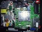
There are 11 high zoomable resolution close up photos totally,to see all the details.First one shows the the entire board.
The attached low resolution you can see the red marked audio connector.
First of all I need to indentify the complete audio circuit that makes possible that the sound can be heared.After that I suppose that I will test with the multimeter all the components that compound that entire circuit.
Wich is your step by step procedure to repair it?
What components make the audio circuit exactly?
Thanks in advance.
I know things about computers repairing not only my own PC at hardware failure and software level inst-desinstall(OS),but also when a friend or friend of that friend ask help and Im in the right position to give it.
Despite that,in electronics im quite green,so for sure I will need all the brains around and all the possible patience that a person or human being can hold inside.
So I explain the facts, suddenly the TV start making a strange sound to the speakers,than there the sound has gone.The speakers I have checked them connecting to other device.The audio jack output also does not work because I have tested with an earphone.
The exact tv model and info are:
Blaupunkt TV,model # W23/173I-GB-FHBKUP-DE
Ref B23C173TCFHD
Product code BW23R173BFBKPE404
Serial Number BW23R173BFBKPE404-107426 00808
Motherboard serial t.msd309.28b
Photos link to see the motherboard:
https://plus.google.com/photos/1027...6079107625735817218&oid=102793503591974069148
https://plus.google.com/photos/1027...6079108071896586770&oid=102793503591974069148
https://plus.google.com/photos/1027...6079108387635073554&oid=102793503591974069148
https://plus.google.com/photos/1027...6079108753207936914&oid=102793503591974069148
https://plus.google.com/photos/1027...6079109117947711538&oid=102793503591974069148
https://plus.google.com/photos/1027...6079109475267788786&oid=102793503591974069148
https://plus.google.com/photos/1027...6079109887551514674&oid=102793503591974069148
https://plus.google.com/photos/1027...6079110207183580290&oid=102793503591974069148
https://plus.google.com/photos/1027...6079110569102090482&oid=102793503591974069148
https://plus.google.com/photos/1027...6079107550650379634&oid=102793503591974069148
https://plus.google.com/photos/1027...6079107148706017746&oid=102793503591974069148
There are 11 high zoomable resolution close up photos totally,to see all the details.First one shows the the entire board.
The attached low resolution you can see the red marked audio connector.
First of all I need to indentify the complete audio circuit that makes possible that the sound can be heared.After that I suppose that I will test with the multimeter all the components that compound that entire circuit.
Wich is your step by step procedure to repair it?
What components make the audio circuit exactly?
Thanks in advance.