Continue to Site

Welcome to EDAboard.com

Welcome to our site! EDAboard.com is an international Electronics Discussion Forum focused on EDA software, circuits, schematics, books, theory, papers, asic, pld, 8051, DSP, Network, RF, Analog Design, PCB, Service Manuals... and a whole lot more! To participate you need to register. Registration is free. Click here to register now.

BJT mixer design for AM receiver

Status
Not open for further replies.

froten

Member level 3
Joined
Jun 17, 2006
Messages
56
Helped
1
Reputation
2
Reaction score
1
Trophy points
1,288
Activity points
1,798
Hi all,

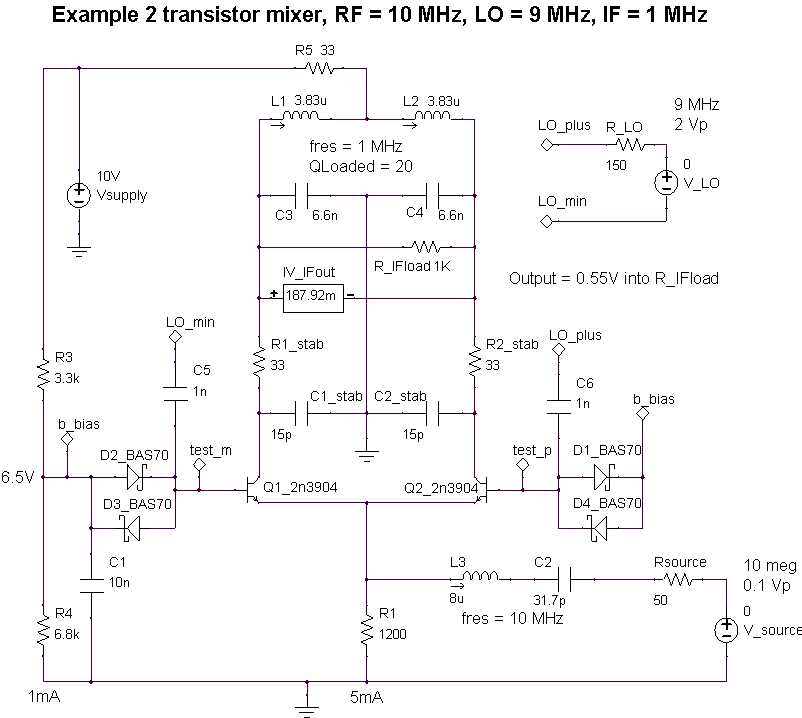
I trying to design a simple BJT mixer AM receiver. I tried many circuits found on the internet but I want to design my own circuit with the LO injected through the emitter and the IF out through tuned circuit on the collector, but I have quision:

What is the non-linearity that should be used? is it V-I of the base-emitter junction, saturation regon or cutoff regon.

this is just a simple circuit, so i'm not woorying about IP3 strong stations ........

any help is very appreciated.
 
Last edited:

Hello,

Such an arrangement may work, but the conversion efficiency will be low. For best conversion efficiency, you should drive the emitter hard, so the transistor goes on and off. So you are switching the BE junction. You have to drive the emitter from a low impedance source to get some conversion gain.

A disadvantage is that the noise from the LO appears in the band of interest, hence reducing the noise figure of the single transistor mixer.

If you use a free running oscillator with a high Q LC-circuit, you may drive directly from the LC circuit (via a tap on the inductance if the inductor is connected to ground). The Q factor of the LC tuning circuit will remove noise. Off course this doesn’t help in case of a zero IF receiver. If you plan to use 455 kHz as IF, it will reduce the LO noise that enters the mixer.

A high Q parallel LC circuit will also provide low impedance to the emitter of the mixer (for the reception frequency) in case of, for example, 455 kHz IF.

Note that there will be feed through from the emitter to the base, so when you connect an antenna to the mixer, you may hear the LO on another receiver.

If possible, try to build a two transistor mixer (differential pair, balanced mixer). Signal is fed to the emitters, LO is fed to the two bases (differentially), output is taken from the collector(s).
 

At this type of mixer very important is to provide the right impedance's at RF, LO and IF ports.
To prevent oscillations the IF port should be a short circuit at both LO and RF frequencies, and also should provide (if is possible) some short at image frequency.
The RF input should be matched to the RF frequency to maximize conversion gain and noise figure, but also should be low impedance at IF frequency, to prevent that the noise at the IF frequency is not amplified and added to the output.
 

hello Vfone,

I fully agree with you, regarding the impedances. It was the main reason for suggesting a 2 transistor approach where you have some built-in isolation between the RF and LO ports.

After experimenting with troublesome single transistor circuits, I soon started with the 2-transistor circuit (RF input at the emitters). By clipping the LO signal (fed differentially at the bases) with schottky diodes, the noise behavior improved significantly. My favorite transistor for such RF experiments at that time was BF199.
 

Thanks all for the help.

WimRFP, could you please provide more details (or circuits) for the design of two transistor differential mixer? I have only examples for 3 transistor diffrentail mixer in some of my text books.
 

Hello,

Please find below an example of a two-transistor mixer.

The transistors function as current switches. So the RF current is switched to the left or right side, dictated by the LO signal.

The IF circuit provides low impedance, except for the IF frequency. The "stab" components are theoretically spoken not required, but due to parasitic components (capacitors, inductors), the impedance of the IF circuit may show peaks at unexpected frequency. This reduces the dynamic range and or stability of the circuit.

When I built such a circuit, I used an inductive coupling to the IF filter. L1 and L2 are on one core with total inductance of 2*L1.

The 4 diodes guarantee low impedance seen from the bases. As the transistors are in common base configuration (seen from the RF source), the bases should see low impedance. If you don't know the behaviour of your LO, the diode trick guarantees fast switching, low impedance and attenuates LO noise (that is in the RF or image band). When you use this circuit at LO frequency in the range of 1 MHz, you may use 1n4148 or 1N914, etc (these are cheap and easy to get).

In practice you may drive the LO input via a transformer (center tap is not required). When you use a free running LC oscillator, you may use a coupling loop that goes directly to the LO inputs.

You can drive this circuit asymmetrically, but this reduces the LO to RF isolation significantly. It is not recommended to do this.

The RF input impedance is low. This is because of the common base that has parallel feedback. You should think of 13 Ohms. For proper operation it is good to make sure that the impedance seen from the emitters is high for harmonics of the LO. Therefore I used a series resonant circuit in the RF chain in this example.

When you build such a circuit, you will notice low insertion gain and high noise at IF. When you increase the LO power the transistors start to switch. This will result in a reduction of noise and increase of insertion gain. Without input matching (so driving from a 50 Ohms source), you may expect about 7 dB insertion gain. Increasing the IF load will increase the insertion gain. Using RF input matching also increases the gain also.

I remember from my practical circuits with BF199, I had just over 10 dB gain (from RF to IF).


Good luck with the descrete mixer design!

Wim
 
Status
Not open for further replies.

Similar threads

Part and Inventory Search

Welcome to EDABoard.com

Sponsor

Back
Top