Continue to Site

Welcome to EDAboard.com

Welcome to our site! EDAboard.com is an international Electronics Discussion Forum focused on EDA software, circuits, schematics, books, theory, papers, asic, pld, 8051, DSP, Network, RF, Analog Design, PCB, Service Manuals... and a whole lot more! To participate you need to register. Registration is free. Click here to register now.

BJT for the lowest phase noise XTAL oscillator

Status
Not open for further replies.
Look at the size of these sapphire oszillators and at the effect of a buffer stage.

Paralleling 2 transistors depends on the type , some experimenting is needed

Added after 1 hours 57 minutes:

No, HFe of the transistors will not bee the same, and this is only applicable for flicker noise in primary standards, and there a FET up to 150 MHz is the better choice.

Above these are typically VCOs and the loop takes care of the flicker noise
 

From my work on VHF crystal oscillators ( Butler two transistor oscillator-amateur radio ones), it pays to look at the possible noise sources in oscillators. I found gains were made by extra decoupling, replacing noise generating resistors by inductors, making the transistors operate in a linear region (by using diode limiters in my case). Further noise reductions were made by filtering supplies.

There are so many areas to look at.

Even getting "good" crystals can be an issue. Crystals that are aged properly, and have the turnover point where one requests it (and within the price range of a hobbyist). I have starting sourcing some crystals from the Czech republic, so will see what they are like.

I didnt run simulations, but measurements on a spec analyser indicated the changes made noise improvements. I came up against the instrument being the limiting factor.
The changes may not be optimum, but they were improvements.

Looking at oscillators is always an ongoing project

Kevin ZL1UJG
 

Correct, i work more on VCOs now up tp mm waves
 

Hi,
In Oscillators where active devices ( eg bfr93 and others) have gain up into the multi - GHz region, there is always the possibility of unwanted oscillations/ parasitics occuring.
I notice in some oscillators (only a few designs) have various extra low value resistors to reduce the probability of unwanted things occuring. (Anti-parasitic components) These are usually in the collector and base circuits, to dampen resonances (?)

When parasitics occur what can they show up as?

Kevin
ZL1UJG
 

biggesst problem, and the reason for thing like resistors, are the various unwanted resonances that can occur. If you are sweeping the frequency, and there is a small resonance in say the varactor circuit, you can have a case where the oscillation conditions are satisfied at TWO simultaneous frequencies. You then end up with sudden hops in frequency, or non-monotonic tuning. This, of course, causes havoc in most PLL or other systems, so you tend to use only very simple circuitry.

Adding resistors can seriously degrade the Q of the tuning circuits, so you have to be very careful where you put them if you need good phase noise.
 

The first thing to do is not to take a transistor with an unnecessary high fT and to have a clean layout where the transistor does not oscillate without the resonator. Connect a spectrum analyzer to the output and monitor this. Grounded base circuits are often highly unstable. Adding resistors increases the noise floor. It is best to use a CAD tool to simulate the circuit using real components with their parasitic inductors and soldering resistors, typically 0.2 Ohm. A good indication is if the oscillator oscillates for off the wanted frequency or at several frequencies (multi mode operation)
 

Hi,
Looking at **broken link removed** , they seem to state that the crystal should have some capacitive loading specification, to resonate on frequency.

I was under the impression that the crystals were series resonant in that type of circuit, (neglecting any component in series for specifically tuning frequency)

There is an article at the Synergy website with simulation figures for the phase noise of a Grounded Base Butler, using a BFR96 with diode clamp, which gives very good figures.

The crystal specification is quite different to what I have seen. I wonder if thats for a SC Cut crystal.

The crystals I have got from the Czech Republic, seem to be doing the job. I had aging issues with some local product, but this firm seems to supply "what one asks for".

Kevin
 

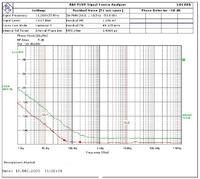
To measure phase noise I have built me a DC-receiver with a DMB in the front end. This DBM is driven by two 'the same' oscillators with amplitude differences of > 10 dB.
With this tool I am able to measure down to -170 dB from 200 Hz upwards and down to -150 dB @ 50 Hz from the carrier. Moreover I am able 'to look' down to dc.
For callibration I went to 'a friend' who gave me entrance to a R&S FSUB Signal Source Analyser.
The red plot is one of my best oscillators.... When I compare this plot with the plots I find at this thread, I'm disapointed about the results, but I'm sure that this oscillator should be "very good". In the application I did not see any oscillator perform better.

Am I doing something wrong or what?

In the next posting I will try to upload the plots.....

Added after 11 minutes:

I give up trying to get the plots. I'm working on Internet from the first beginning, but to get a .jpg-file uploaded to here......

Added after 23 seconds:

I give up trying to get the plots. I'm working on Internet from the first beginning, but to get a .jpg-file uploaded to here......

Added after 23 minutes:

Nog EEN keer:
 

Hi,

anyone heard something new about the guy that claimed -137dBc at 1Hz deviation from the 10MHz carrier?

Schmocki
 

N1UL: doc files doesn't make my very happy, because word or other doc compatible word processing programs tend to be slow.

I like to see pictures directly in my web reader. It's faster and the files to download is smaller. Even the PDF files is better than doc because most OS have native support for it (windows not mentioned).
For windows:

So here I have converted the doc files to PNG pictures using FSIV and used Open Office to create an PDF file:**broken link removed** is a light viewer.

For the record: JPG pictures shouldn't be used on schematics, tables, graphs (as shown above). The better format for this is PNG that takes less space and doesn't get blurry.
 

Re: bft66 spice

N1UL said:
In the DC circuit, the PNP transistor samples the DC current up to some offset, and within the loop gain and bandwidth compensates this. The third transistor act as a temperature stabilizing diode. It inverts the voltage drop at the output, including the noise by -180 deg and feeds it back so canceling these contributions to some high degree

Ulrich, how about the noise of the two BC857?
Don't they introduce additional noise? Of course they keep the DC (and low frequency) current of the oscillator transistor stable against its Vbe variations, but they regulate the current to ((Vbias-Vbe3)*4700/(4700+6800) + Vbe3 - Vbe2) / 270 ohms.
So if we consider Vbias to be noise free and the variations of Vbe1 (of the oscillator transistor) to be neglectable due to the high feedback gain, the residual variations in the bias current of the oscillator transistor are (Vbe2 + 0.59*Vbe3) / 270 ohms. As noise adds geometrically one gets 1.16*VbeNoise/270ohms as the noise current of the oscillator transistor, right?

Also the temperature compensation by the third transistor is a bit poor (only compensates about 55% of the temperature associated Vbe variations) as only about 60% of its Vbe change is resembled on the 6k8 resistor where the base of the second transistor is connected, and due to the about 8% higher temperature sensitivity of the second transistor caused by it having only one fifth of the collector current of the third transistor (I assumed a DC current gain of 90 for the oscillator transistor).

Schmocki
 

Re: bft66 spice

I think that the amplitude stabilisation in an oscillator is very important for low noise (Xtal-)oscillators. I jumpt through this thread but cannot find any suggestion in this field, or do I miss subjects?
 

Hi,

it seems you missed most of the subject :)

The circuit Ulrich posted here serves in stabilising the bias of the oscillator transistor. As the oscillator transistor also is the part that limits the amplitude, the amplitude variations are also minimised by this circuit.

Regards,
Schmocki
 

Hi,

it seems you missed most of the subject :)

The circuit Ulrich posted here serves in stabilising the bias of the oscillator transistor. As the oscillator transistor also is the part that limits the amplitude, the amplitude variations are also minimised by this circuit.

Regards,
Schmocki

Oh, sure, but I cannot find the circuit....
Regards,
Herb.
 

Oh, sure, but I cannot find the circuit....
Regards,
Herb.

Oh, I'm sorry, but if I look at the curves in Ulrich's oscillator on 155 MHz and compare them with my simple Clapp-oscillator with a FET on 11 MHz, they are only a few dB better. Should I follow another approach at 11 MHz?
 

You might wish to study the theory more. If you have an oscillator with phase noise X at 155 MHz, and oscillator with the same phase noise at 11 MHz will need to be 23 dB better. 20 Log N, resonator Q(f), etc, ya know.
 

You might wish to study the theory more. If you have an oscillator with phase noise X at 155 MHz, and oscillator with the same phase noise at 11 MHz will need to be 23 dB better. 20 Log N, resonator Q(f), etc, ya know.

This is what I mean. My FET-oscillator (with 7 components) is only 10 dB worse than the rather complicated one of Ulrich.
BTW I know the theory already for about 50 years.....;-)
Regards,
Herb.
 

Sometimes to get 10 dB reduction in phase noise is priceless, and few components more means nothing.
Ulrich's approach using feedback for phase noise improvement was proved, patented, and used already in many applications for many years.
 

This is what I mean. My FET-oscillator (with 7 components) is only 10 dB worse than the rather complicated one of Ulrich.
BTW I know the theory already for about 50 years.....;-)
Regards,
Herb.

I am not sure we are getting thru the language barrier. Build your fet oscillator at 155 Mhz, measure its phase noise, and then brag about it!

Anyone can build a good oscillator at 11 Mhz, where crystals are available with unbelieveable Q's.
 

I am not sure we are getting thru the language barrier. Build your fet oscillator at 155 Mhz, measure its phase noise, and then brag about it!

Anyone can build a good oscillator at 11 Mhz, where crystals are available with unbelieveable Q's.

On this thread I have read that FETs should only be used below about 100 MHz. At 10 MHz a FET should be better than a BJT. Is this correct? You all seem to have the information I'm looking for....
BTW, don't say that anyone can build a good oscillator at 11 MHz... This is less simple as it seems to be. If you know how, please give me the info how to fix it.
Regards,
Herb.
 

Status
Not open for further replies.

Part and Inventory Search

Welcome to EDABoard.com

Sponsor

Back
Top