Nerdie
Newbie level 5
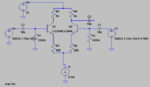
Im trying to design a bjt amplifier with a gain of 10. However, there are some problems that I cannot answer myself.
First of all, as you can see from my design, there are 2 big resistances at each base and I dont know their functionality exactly. I guess they are there for draining current from ground in roder to turn on the BJT, but why should they have to be so big resistances?
Secondly, there has to be a current source for a huge output resistance which helps the circuit to work properly I guess. However, what should be the amount of the current? Does it affect anything rather than voltages at nodes in the circuit?
Lastly, I have to design the current source with a bjt. However, I dont know how to dc bias the bjt, because of current bias which gives negative voltage levels at emitter side.
If you have an answer to any of the problems above, I would be so glad.