Continue to Site

Welcome to EDAboard.com

Welcome to our site! EDAboard.com is an international Electronics Discussion Forum focused on EDA software, circuits, schematics, books, theory, papers, asic, pld, 8051, DSP, Network, RF, Analog Design, PCB, Service Manuals... and a whole lot more! To participate you need to register. Registration is free. Click here to register now.

[SOLVED] BJT DC Gain, Ic and Vce

Status
Not open for further replies.

tahir4awan

Full Member level 4
Joined
Nov 29, 2010
Messages
208
Helped
16
Reputation
32
Reaction score
17
Trophy points
1,308
Location
Germany
Activity points
3,084
Hello Friends I have a question regarding transistor operation hope you guys help me.

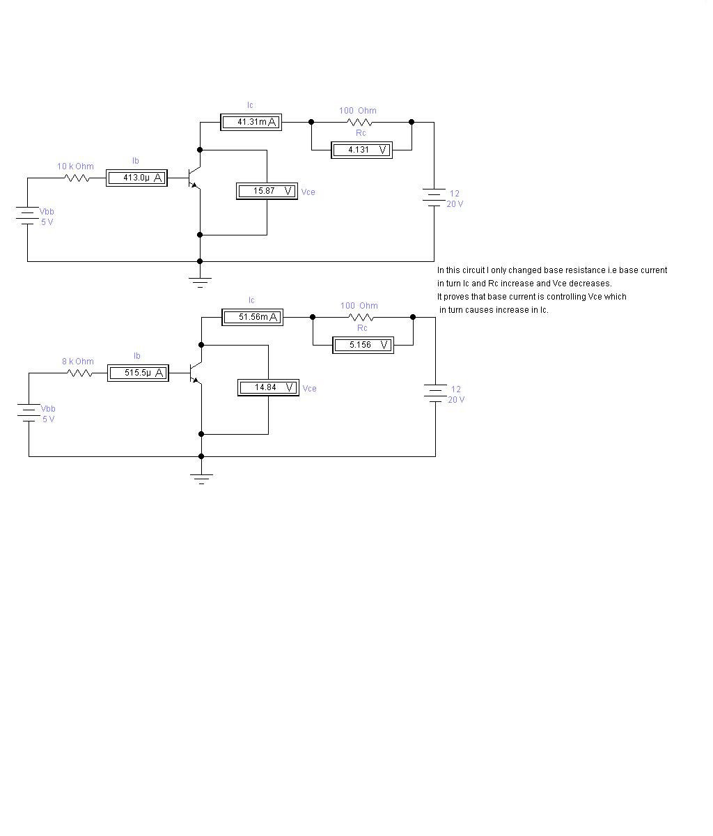
As we know in common emitter configuration when base current increases , collector current also increases while Vce collector to emitter voltage decreases.
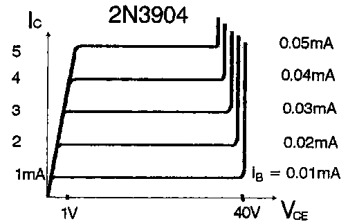
I was reading 2N3904 data sheet I was confused when I saw Hfe (DC gain) table.
There was given different Hfe for different Ic but it was strange that Vce is constant for all ranges of Ic and Hfe.
How it is possible that variation Ic is not affecting Vce.
Well this is my second post so I cannot insert links so please read data sheet of 2N3904 transistor .
 

That Vce is only a juction voltage, just like the diode, when diode on, the voltage is keep contant about 0.7V, but the current is varied according to the other circuits. The I=(Vcc-0.7V)/(Re+Rc)
 

Vce does not necessarily drop as Ic increases - it depends on the circuit. For generating data sheets Vce is usually held at fixed voltages while Ib is swept.

Keith
 

Thanks for reply but I don't agree with you answer. In Ic vs Vce graph it is Vce which changes because at fixed base voltage when you increase Vcc the Ic will vary to some level but then it becomes constant.At the same time Vce will increase.
If Vce is a constant as you said then it will be a simple diode. It is the Vce which causes the transistor action.
Its very simple Vce is a variable resistor controlled by base current. Increase in base current causes decease in Vce voltage so Ic also increases.
The voltage drop at Vce is from 0.2 to 0.3 volts at saturation which is ideally considered 0 in calculation.
It is not a PN junction drop as Vbe because Vce is collector to emitter voltage and collector - emitter are both N types.
 

What graph are you referring to? This, for example:


has a fixed Vce. I cannot see an Ic vs Vce graph.

Keith.
 

Hi tahir4awan
the following statement certainly is NOT true

Its very simple Vce is a variable resistor controlled by base current. Increase in base current causes decease in Vce voltage so Ic also increases.

*The BJT (in contrast to a FET) cannot be seen as a "variable resistor" controlled by a base current.
The BJT is a strong NONLINEAR device and cannot be handled based on ohms law.

*However, as far as your first posting is concerned, the answer is very simple:
You were referring to a common emitter configuration (and I assume: with a collector resistance Rc).
Thus, if Ic increases the voltage drop across Rc increases and, therefore, the voltage across the BJT must decrease (for constant supply Vcc).
 
I made a simple circuit which will clear my question.

Second you asked me about Ic vs Vce graph please see image .
 

Hi tahir4awan,

for my opinion, your main question was:

How it is possible that variation Ic is not affecting Vce.

Here is my answer - it touches BJT basics which can be found in each textbook:
As mentioned already, the BJT cannot be treated as an ohmic resistor as it is an active non-linear device.
The BJT can be treated as a base current controlled current source: Ic=Hfe*Ib - and as the second figure shows: Nearly independent on Vce (if Vce>Vce min).
But consider that this graph is for the transistor alone - without any other circuitry.
Now, when there is a resistor Rc and a fixed supply voltage Vcc, the voltage Vce cannot remain constant because the voltage across Rc increases (because of an Ib increase).
Thus, the BJT is not responsible for the Vce change, rather it is the ohmic law applied to Rc.
That's the "secret" of the load line that can be drawn within the graph above.
I hope it helps a bit.
LvW
 
Just to add, what this image shows:

https://obrazki.elektroda.pl/22_1291331607.jpg

is that when the current through a 100 ohm resistor is 41mA you get a 4.1V drop and when it is 51mA there is a 5.1V drop i.e. ohms law. It doesn't tell you much about the transistor characteristics. Replace the resistor with 0.001 ohms and try a bigger sweep of the resistor value on the base and you might get a better idea of what is happening with the transistor.

This graph:

https://obrazki.elektroda.pl/66_1291331765.gif

which isn't from a "real" transistor does not support the statement you made "when base current increases , collector current also increases while Vce collector to emitter voltage decreases". In fact it shows that the opposite can be the case. If you fix Vce and choose a base current, you can look up the collector current. You can then choose a different base current and look up a new value of collector current without changing Vce.

As mentioned, any text book will contain a description of the operation of a bipolar transistor and there will be many sources on the internet.

Think of it as a current controlled current source. The base current is amplified, for example by a factor of 100, to produce the collector current. A perfect current source will produce the same current no matter what load is applied to it. That is precisely what your graph is showing above. A perfect current source will plot as a horizontal line on a voltage/current plot i.e. its resistance is infinite. In reality the horizontal lines will have a slope to them due to the "Early effect" but that is another problem.

Keith.
 
Most characteristic curves in a datasheet are x-y-plots following this simpe scheme:

The is variable at the horizontal axis is varied (also called independant variable), the variable at the vertical axis is observed (dependant variable). One or more additional parameters are either fixed, or stepped through a list of values, e.g. Ib in the shown Ic versus Vce chart. The measurement circuit has to be choosen in a way, that the specified conditions are achieved. If e.g. Vce is set to a particular value, the measurement circuit has to keep it constant. It's absurd to ask, why Vce doesn't change.

A characteristic curve usually does not describe the behaviour in a particular amplifier circuit.
 
Status
Not open for further replies.

Similar threads

Part and Inventory Search

Welcome to EDABoard.com

Sponsor

Back
Top