Continue to Site

Welcome to EDAboard.com

Welcome to our site! EDAboard.com is an international Electronics Discussion Forum focused on EDA software, circuits, schematics, books, theory, papers, asic, pld, 8051, DSP, Network, RF, Analog Design, PCB, Service Manuals... and a whole lot more! To participate you need to register. Registration is free. Click here to register now.

Beadboard Direct Coversion RX, how to eliminate noise and unwanted sounds

Status
Not open for further replies.

truffaldino

Junior Member level 3
Joined
Feb 14, 2016
Messages
28
Helped
0
Reputation
0
Reaction score
0
Trophy points
1
Activity points
295
Hello,

I have collected a direct conversion receiver on 3 breadboards: the first one contains rf stage, the second one contains opamp audio preamplifier/bandpass filter and the third LM386 audio amp in minimal configuration with gain 20.

The rf part is based on NE612 famous mixer. The receiver works quite weel (I can hear 10 nanowatt beeping transmitter from other end of my appartment) but it makes a noise or a steady continous sound unless I put my fingers on ne612 chip and connecting wires between RF breadboard and audio preamp breadboard.

I know that one should not make rf circuits on breadboard, but how can one deal with such problems?

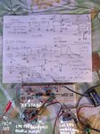
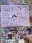
I am attaching picture of schematics and the circuit.

I would like to avoid soldering etc.

Thanks in advance
Truffaldino

Thanks in advance
 

Attachments

  • Breadboard RX.JPG
    Breadboard RX.JPG
    492.9 KB · Views: 94

Your bandpass amplifier has its (-) input floating high since it has no DC connection to the output of the opamp.
Your bandpass amplifier has VERY gradual slopes and is almost useless. I simulated it with a single input instead of your differential inputs and my opamps have a dual polarity supply to simplify biasing.
You need a Multiple Feedback Bandpass Filter that I show.

- - - Updated - - -

You forgot to describe the noise and unwanted sounds. The lousy old LM158 and LM358 are noisy (hiss) and have crossover distortion (fuzz) which might be the noises you hear.
 

Attachments

  • filters.png
    filters.png
    41.3 KB · Views: 74

Your bandpass amplifier has its (-) input floating high since it has no DC connection to the output of the opamp.
Your bandpass amplifier has VERY gradual slopes and is almost useless. I simulated it with a single input instead of your differential inputs and my opamps have a dual polarity supply to simplify biasing.
You need a Multiple Feedback Bandpass Filter that I show.

- - - Updated - - -

You forgot to describe the noise and unwanted sounds. The lousy old LM158 and LM358 are noisy (hiss) and have crossover distortion (fuzz) which might be the noises you hear.

Thanks Audioguru,

Sorry for wrong circuit on the picture I have posted. This is a drawing mistake. In fact my real connections to opamp (-) is identical to the ones you have proposed in your post. Here I attach a circuit drawn in proteus with simulation results similar to yours.

In this circuit (-) of opamp is connected to 1st output of mixer and (+) to the 2nd one (2nd has the same aplitude and opposite phase).

The graph on the image shows voltage gain vs frequency in linear scale.

About unwanted sound I hear: This seems to be a continuous sound of frequency that is close to the beep frequency I expect.
I think, due to bandpass filtering this is a filtered noise with mean frequency close to the one I expect for signal.

Thanks
Truffaldino
 

Attachments

  • audio bandpass amp.jpg
    audio bandpass amp.jpg
    162 KB · Views: 89

Your corrected schematic shows a Multiple Feedback Bandpass Filter that I recommended and showed. Since it has a very narrow bandpass at its peak then I think it plays that frequency caused by noise from the awful noisy and distorted opamp you are using.
 

Your corrected schematic shows a Multiple Feedback Bandpass Filter that I recommended and showed. Since it has a very narrow bandpass at its peak then I think it plays that frequency caused by noise from the awful noisy and distorted opamp you are using.

Dear Audioguru,

Which opamp do you suggest to use instead?

I have also tried TL082 and LM324 with similar results (I think LM324 and LM158 are in fact the same).

Truffaldino
 

Your schematic does not show a power supply voltage. Why? It might be less than the 7V minimum for a TL082.

You talk about multiple opamps instead of single opamps. Maybe you are not disabling unused opamps properly which is causing them to oscillate.

An OPA134 is a good low noise single opamp (OPA2134 dual or UPA4134 quad) with a 5 minimum supply but it might oscillate at a high frequency if it is used on a solderless breadboard.

Thanks Audioguru,

I am using proteus schematics/simulation just to pick up right values of resistors/capacitors. I am using 9v -14v supply on the breadboard.

I also try to disable rest of opamps by grounding (+) input and connecting (-) input with the output (this is a kind of ground "voltage follower"). Is this correct way to disable?

I have just changed a RF part of circuit and now receiver is working (not so good, there still significant background noise, but it is working) with LM158 and TL082. It would be nice to futher reduce the noise, maybe I should try a kind of digital filtering on PC or with a microcontroller.

I am attachning the image of corrected circuit.

Truffaldino
 

Attachments

  • Breadboard RX.JPG
    Breadboard RX.JPG
    497.7 KB · Views: 84
Last edited:

Just an observation since you already know breadboard RF is "tricky"
You seem to have a lot of potential for pickup and parasitic interference.
One thing I'd do if I had to work on breadboard would be to use short
tight links - right angled and pressed flat into tight breadboard holes - ideally
on a new board. I'd try and get a good design first (before struggling with breadboard)
then test each module seperately before building a prototype onto
veroboard. Also try not to wrap wires around chips if you can.
This may not be possible I realise but I thought it worth a mention.
My experience is that breadboard is really only reliable for a very small number of
components and contacts become poor very quickly.
 
Status
Not open for further replies.

Part and Inventory Search

Welcome to EDABoard.com

Sponsor

Back
Top