Continue to Site

Welcome to EDAboard.com

Welcome to our site! EDAboard.com is an international Electronics Discussion Forum focused on EDA software, circuits, schematics, books, theory, papers, asic, pld, 8051, DSP, Network, RF, Analog Design, PCB, Service Manuals... and a whole lot more! To participate you need to register. Registration is free. Click here to register now.

Battery Charger Circuit

Status
Not open for further replies.

gauravkothari23

Advanced Member level 2
Joined
Mar 21, 2015
Messages
640
Helped
5
Reputation
10
Reaction score
4
Trophy points
1,298
Activity points
6,922
Hi All,
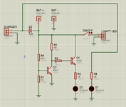
I Am trying to make a Battery Charger circuit with Bat LOW Indication using LED (Circuit Attached).
Battery Used: 4V Lead Acid 4 Amp
As per the circuit design, D3 LED glows when battery level goes below 3.4V (Works Perfect)
and D1 LED glows when charger in connected.
but when 5.2V 1.5 Amp charger is connected, D2 Diode SS24, which is connected in series, gets extremely hot even at 1.2 Amps.
Why the diode gets hot even at 1.2 Amps, when it is being rated for 2 Amps.
While charging, i keep the output LED OFF
--- Updated ---

The Diode D2 is used to to avoid D1 LED glow when charger is not connected.
 

Attachments

  • Bat Chrg.png
    Bat Chrg.png
    26.9 KB · Views: 103
Last edited:

Did you care about the "Thermal Characteristics" informations given in the datasheet?

Klaus
yes, i had gone through, but did not understood that part. which says,
RθJA 75 °C/W
RθJL 17 °C/W

what does it mean.
--- Updated ---

what i have understood is:
RθJL: junction and device lead.
but which junction
--- Updated ---

what diode is recommended is such case.
or rather than using a diode, how can i keep the LED D1 OFF, when charger is not connected, and ON when charger is connected.
 
Last edited:

Hi,

Seems I´m using a different datasheet.
Give a link to your datasheet, so we can discuss about it.

genrally:
J = junction = silicon die inside
A = ambient
L = lead

calculation is like ohmic resistors.
example: 1.5W * 75°C/W (JA) = 112.5°C temperature rise.
So if ambient temperature is 40°C and you have a (JA) rise of 112.5°C then the junction (chip) has a temperature of 152.5°C.

Klaus
OK, got it.
This is the link to the datasheet.

so in my case,
the power dissiaption is 6W, so the (JA) would be around 450 degree, which cannot be used.

what other diodes can i use, or any other circuit,
because the diode is used only to keep the LED D1 OFF without charger connected.
--- Updated ---

so where are this diodes used, so as per the datasheet, the diodes working temp is upto 150 C.
even at 1.5W of power dissipation, if the diode crosses the limit, where can we use this diodes.
 
Last edited:

Please understand that the power dissipation is the voltage dropped across the diode multiplied by the current through it, regardless of the diode type. V * I will give you the power dissipation in W. The thermal rating is the temperature rise in degrees Celsius for each Watt dissipated.
You either have to live with the temperature rise or find a way to conduct the heat away, a different type of diode won't help unless it can do that.

Brian.
 

Hi,

did you read the datasheet information:
"Note
(1) PCB mounted with 0.55" x 0.55" (14 mm x 14 mm) copper pad areas"

The diode power dissipation is rather 0.6W than 6W.

And "hot" is relative. You may find 50°C to be hot, the diode may start with 100°C and it can withstand 150°C junction temperature.

If you think that the disspation is too high, you still have the option to use so called "ideal diode" ICs.

Klaus
no, the diode is not around 100 C, if it was around 100 C, there was not an issue,
but diode gets so hot that if kept running for 10 minutes, the solder also gets melted a bit. if i try to push the diode a bit harder, the diode leaves it place.
 

Status
Not open for further replies.

Part and Inventory Search

Welcome to EDABoard.com

Sponsor

Back
Top