oldsamples
Newbie level 3

Hello Experts,
I am trying to simulate very basic structure and I cannot get it right.
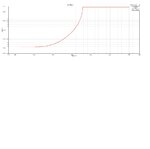
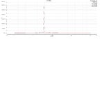
My structure is a regular cylindrical resonator. I want the TE11 mode. My resonance frequency is 2.0 GHz. The dimensions are: radius 0.05m, length of the cylinder 0.156m. I have checked the formulas and I have Eigenmode simulation confirming the mode. So next I want to make the driven modal solution for the same structure and obtain the s11 parameter for frequency around the resonance frequency. So I make a sweep and instead of drop of s11(in dB) I get values that are close to zero..no resonance found whatsoever. The critical frvalue of this particular waveguide is around 1.75GHz. When I sweep from 0.1 to 2 Ghz I get drop of S11 until the critical frequency and after that 0 (see the picture). Shouldn't be the opposite since the all power is reflected when the critical waveguide frequency is not met. For the sweep I use the "discrete" setting. The discretization is made for 4Ghz setting.
Thanks in advance,


