Continue to Site

Welcome to EDAboard.com

Welcome to our site! EDAboard.com is an international Electronics Discussion Forum focused on EDA software, circuits, schematics, books, theory, papers, asic, pld, 8051, DSP, Network, RF, Analog Design, PCB, Service Manuals... and a whole lot more! To participate you need to register. Registration is free. Click here to register now.

Bandwidth of baseband filter in homodyne receiver

Status
Not open for further replies.

mtwieg

Advanced Member level 6
Joined
Jan 20, 2011
Messages
3,835
Helped
1,310
Reputation
2,626
Reaction score
1,405
Trophy points
1,393
Activity points
29,372
Hello, hopefully this will be an easy one for you guys...

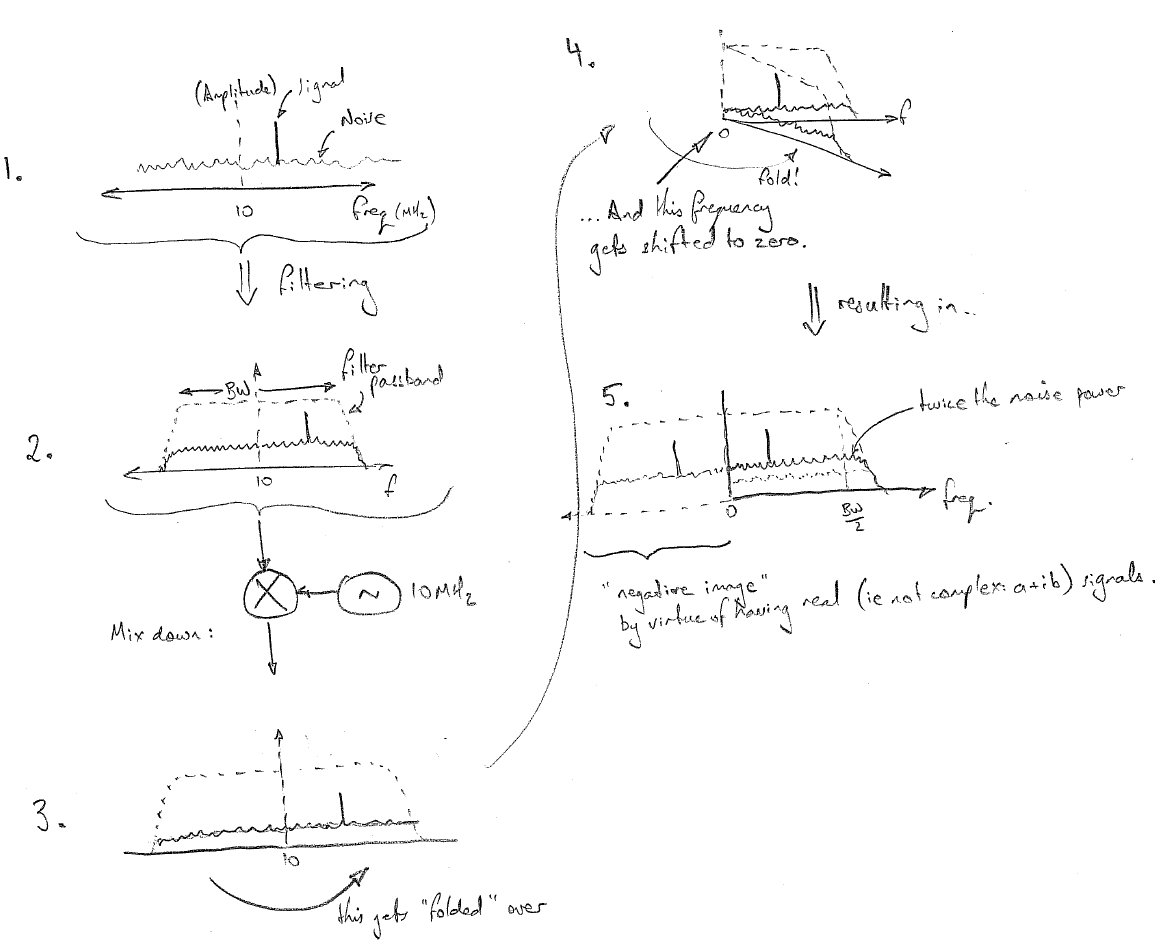
I'm testing a zero IF/homodyne receiver I've built, and am a bit confused that I am getting about 3dB more noise than expected. I'm converting from 10MHz, and am interested in selecting a bandwidth of 100KHz (so f=9.95-10.05MHz), so I made a baseband lowpass filter with a cutoff frequency of 100KHz, thinking that would select the proper bandwidth. But I'm pretty sure that's wrong, since in reality all the signal content between 9.9-10.1MHz will end up in my passband, hence why I'm seeing +3dB noise over what I expect from 100KHz of bandwidth. So should I reduce the cutoff frequency of my baseband filter to 50KHz? On paper this will allow my desired 100KHz of bandwidth through, and give the noise I expect, but I'm having trouble just believing that a lowpass filter with fc=50KHz can pass signals with BW=100KHz...

Any advice?
 

Hey mtwieg!

If I understand what you're saying correctly - yes, your suspicions are correct... You can view traditional 'zero-IF' downconversion (i.e. that performed by mixing/multiplying with a local oscillator = 10 MHz) as a spectral 'folding' operation, where the spectrum above AND below your LO frequency get folded on top of one another, with the fold line then being shifted to DC.

Let me attach a sketch to make that a little clearer :)


The noise power in the unwanted [lower, in this case] sideband (and any signals that happen to be there) are added in to the final output spectrum, thereby raising the noise floor by the 3 dB you observed. Unfortunately, fiddling the shape of the passband (assuming it's optimally matched to the signals of interest and no wider than strictly necessary) or LO frequencies doesn't help either - all that does is move the origin of the fold.

There *is* a solution though, and it's alluded to by my note at the end about the real and (possible) complex representations of the mixer output. If complex downconversion (also called quadrature mixing) is performed instead, you can arrange for the unwanted sideband to be intrinsically 'canceled out' in the mixing operation and avoid the problem you're observing. While the cost is a more complicated mixing stage than just a single mixer, for a fixed (and relatively low) IF frequency like yours it can be implemented accurately without much difficulty. You can find references and details on the web by searching for "image rejecting (or rejection) mixers". The "phasing method of SSB generation" also uses the same techniques, so you might find something useful there too.

Good luck :)

(Oh, and it can be done numerically [in DSP] with a little care with filter passbands and ADC sampling strategies as well. You might find some good leads there too!)
 

I am no DSP expert, but I think if you just run the adc at >20 MHz clock speed (2 x the nyquist rate) you can separate negative frequencies from positive frequencies. yes/no?

The noise figure is not 3 dB higher, per se, than with a low IF frequency. It is just that you have both the negative and positive frequencies shown in 0 to 5 MHz baseband.
 

Hey mtwieg!
The noise power in the unwanted [lower, in this case] sideband (and any signals that happen to be there) are added in to the final output spectrum, thereby raising the noise floor by the 3 dB you observed. Unfortunately, fiddling the shape of the passband (assuming it's optimally matched to the signals of interest and no wider than strictly necessary) or LO frequencies doesn't help either - all that does is move the origin of the fold.
So in my case, I only need a baseband filter with a fc of 50KHz in order to recover all the information in the 100KHz BW narrowband signal, correct? Assuming I have quadrature detection, of course. In that case, is there any penalty to my SNR? I should have 100KHz worth of signal, and 100KHz worth of noise, same as the original narrowband signal, correct?
There *is* a solution though, and it's alluded to by my note at the end about the real and (possible) complex representations of the mixer output. If complex downconversion (also called quadrature mixing) is performed instead, you can arrange for the unwanted sideband to be intrinsically 'canceled out' in the mixing operation and avoid the problem you're observing. While the cost is a more complicated mixing stage than just a single mixer, for a fixed (and relatively low) IF frequency like yours it can be implemented accurately without much difficulty. You can find references and details on the web by searching for "image rejecting (or rejection) mixers". The "phasing method of SSB generation" also uses the same techniques, so you might find something useful there too.
Fortunately I've already got I/Q mixers in the hardware, along with baseband filters on each. I expected I'd need them at some point, but I'm not sure what to do with them. In fact, my narrowband signal is pretty much entirely real, so when I set the LO phase correctly I actually will only get signal on the quadrature channel, and nothing but noise on the I channel. So in this case what do I do with the information from the I channel? You mentioned that IQ can be used to "cancel out" the negative frequencies, but I don't understand what you mean there. Your pictures are perfectly clear, but how does IQ demodulation solve the issue with frequency "folding"?

I am no DSP expert, but I think if you just run the adc at >20 MHz clock speed (2 x the nyquist rate) you can separate negative frequencies from positive frequencies. yes/no?

The noise figure is not 3 dB higher, per se, than with a low IF frequency. It is just that you have both the negative and positive frequencies shown in 0 to 5 MHz baseband.
Unfortunately, there's no way I can sample that fast. Best I can do at the moment is 625Ksps (simultaneous samples on the I and Q channels).

I also considered digital IF downconversion as described here:
**broken link removed**
But this requires a good antialiasing BPF at the center frequency, which is inconvenient for me since my fc will likely change arbitrarily.
 
Last edited:

Status
Not open for further replies.

Part and Inventory Search

Welcome to EDABoard.com

Sponsor

Back
Top