Continue to Site

Welcome to EDAboard.com

Welcome to our site! EDAboard.com is an international Electronics Discussion Forum focused on EDA software, circuits, schematics, books, theory, papers, asic, pld, 8051, DSP, Network, RF, Analog Design, PCB, Service Manuals... and a whole lot more! To participate you need to register. Registration is free. Click here to register now.

bandgap curvature desired?

Status
Not open for further replies.

kavitha_rapolu

Junior Member level 3
Joined
Jan 4, 2008
Messages
26
Helped
0
Reputation
0
Reaction score
0
Trophy points
1,281
Activity points
1,460
Is the curvature desired or not desired in bandgap?
 

It depends on your project spec. Curvature compensation needs more design effort and area cost.
 

Hi Kavitha_rapolu,

The curvature of the output voltage generated by Bandgap References comes from non-idealities of the circuit (bipolar, resistors, etc…). The most responsible source of this curvature, in your BGR, is the high-order components of the VBE voltage. This voltage is not perfectly linearly proportional to the temperature.

However, in few words, one of the objectives of temperature compensated voltage/current references is to be stable again temperature variations, or ideally insensitive to temperature variation. Therefore, the output curvature is not desired.

But, as explained by leo_02, if your system requires very high accuracy, you can use techniques available in literature to reduce this curvature.

Best regards.
 

So, Ideally bandgap voltage should be constant with changing temperature.

But which one of the below is better to have
1) bandgap voltage increasing with increase in temperature .
2) bandgap voltage having curvature with increase in temperature.
 

In most of applications, 2) is preferred.
 

Hi kavitha_rapolu,

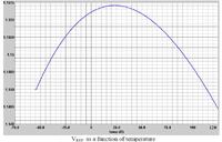
If we are talking about traditional topologies of BGR, the typical curvature is downward concavity (i. e. as shown in figure 1). So, if you properly designed your BGR circuit, the output voltage will not increase if temperature. It will decrease, because the non-ideal terms of VBE will be significant.
So, if I understood well your question options 1) and 2) will not occur.
Regards,


Which one of the following curve would you suggest to have


All the curves are practically the same and all of them can be chosen.
What is your room temperature? Normally it is designed the maximum point (derivative = zero) at the room temperature; e. g. , if Tr = 300 k, the maximum point of output voltage over the temperature range is designed to be at T = 300 K. In such way, you have less output variation at your room temperature. Did you get it?

By the way, are you designing a curvature compensated BGR? Or the increase of VREF in high temperatures was not expected?
 

Thank you. Room temp is 25C. Got it.
I dont know what is meant by curvature compensated BGR. This is the first time i am working on bandgap. My circuit is Fig1 in attachment without R1 and R2. Is it curvature compensated? What is curvature compensation?
Yes the increase of VREF at high temp was not expected . I am trying to figure it out. Any thoughts?
 

Attachments

  • bandgap.pdf
    130 KB · Views: 80

Are u designing the circuit of figure 1 without resistors R1 and R2?
If yes, it is not curvature compensated. One example of curvature compensated Bandgap voltage reference is that one shown in figure 4.
Curvature compensation is a technique that you compensated the curvature with downward concavity of VREF (shown in my first figure), therefore allowing better temperature performance. In other others, you try to cancel this curvature.
Take a look in the bias condition of your bipolar. What is the value of BETA, for your bias conditions????
If it is too low, the base current through the base resistance can create an extra error in the output voltage, generating this increase in high temperatures...
 

Thank you. Can you please explain how base current will effect output voltage?
BETA of npn is 25. ic is 4.5uA
 

Are u using PNP or NPN devices?
BETA = 25 is the maximum value allowed by this bjt? If no, try to bias it with higher BETA.
For example, if your base resistance is not negligible, your output will be proportional to VBE + Rbase*Ibase.
(Rbase*Ibase is usually consider zero,depending of its values, it can damage the temperature performance.
 
Last edited:

I am using NPN. Should i increase current for higher beta?
Also is using vertical NPN better or vertical PNP ?
for PNP with base connected to ground, will there be base current?
 

It depends on... you need to simulate BETA x collector current in order to check the BETA behavior.
This happens wih NPN or PNP... both cases.
Use an ideal BJT device in order to check if it is the responsible for this curvature. I believe it is.
Maybe placing many devices in parallel, you can decrease the base resistance.
 

Status
Not open for further replies.

Similar threads

Part and Inventory Search

Welcome to EDABoard.com

Sponsor

Back
Top