Continue to Site

Welcome to EDAboard.com

Welcome to our site! EDAboard.com is an international Electronics Discussion Forum focused on EDA software, circuits, schematics, books, theory, papers, asic, pld, 8051, DSP, Network, RF, Analog Design, PCB, Service Manuals... and a whole lot more! To participate you need to register. Registration is free. Click here to register now.

automatic college bell program error

Status
Not open for further replies.

khushbu06

Junior Member level 1
Joined
Feb 5, 2012
Messages
15
Helped
0
Reputation
0
Reaction score
0
Trophy points
1,281
Location
gujarat, India
Activity points
1,385
here i am with a new error in my project..
though i have completed my shouldering process of components..
now i have programming error..
here i am attaching my program again.. send me the HEX code of it please....!!!!!

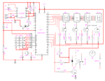
and also attaching the circuit..
 

Attachments

  • ASM program.pdf
    68.3 KB · Views: 60
  • qa-00191--college_bell_circuit.gif
    qa-00191--college_bell_circuit.gif
    28.8 KB · Views: 77

That circuit doesn't look quite right. You've got NPN transistors driving the high-side (+5) of your displays. I think you really want to use PNPs , with the emitters connected to +5 and your collectors going to the displays. I assume your displays are the common-anode type, right?
 

Do not expect anyone to do your homework for you. The program has "0" errors. Try to compile again. For your convinience the same website has an on line compiler too on this link: https://www.8051projects.info/onlineasm.asp
Just upload the asm and get the hex file.
Cheers
 

ya display is common anode type....
now what do i do?
because i don't have enough time for making the project again...!!!
and i also can't understand the working of keyboard...
i have used switches...
i am really confused...!!Image044.jpg
 

i am not like expecting anyone to do my h.w
but i don't have enough time to think of this project deeply...
thats why want help from someone who can clear my query....
:-(
 

Can you ask a more specific question? You can't expect people to just look at your entire program and tell you what's wrong. Does the display work at all? (it might, depending on LED drops, etc.) Are you running this with a debugger or emulator, or are you just trying to debug the entire board as is? Do you have an oscilloscope to look at inputs/outputs?
 

ya display is working but not according to the switches..
i mean when i m pressing 1 then there should be written 1 in display..
and by # and * key my timing will be set..
but i can't even set the time..
and ya oscilloscope is there... even CRO is there too... pulse is created by RTC, that we saw...
after each second display is blinking..
and my professor told that there is no error in display or transistor..
error is in program that i have loaded in IC..
and program is copied and pasted through net.. i haven't made by own-self..
its really now becoming a headache....
 

Well, sorry, but your professor is wrong; there IS an error in your display driver. Those transistors are configured as emitter followers: the voltage at the emitter (the anode of your LEDs) will be the base voltage minus about 0.7V. It might work, but it's not the best way of doing it, it's better to use the transistors as switches, not followers; as I explained before, you really should be using PNPs. Further, you've got a 10K pullup on the output driving Q1, but not on the other transistors. Is that intentional?

As far as debugging your code, it's difficult to debug an entire program all at once; do it in pieces. First, verify that the routine that writes to the display is working properly. Maybe just extract that part of your program and make a test program and write some fixed values to the display. A debugger or emulator would also help.
 

Status
Not open for further replies.

Similar threads

Part and Inventory Search

Welcome to EDABoard.com

Sponsor

Back
Top