Continue to Site

Welcome to EDAboard.com

Welcome to our site! EDAboard.com is an international Electronics Discussion Forum focused on EDA software, circuits, schematics, books, theory, papers, asic, pld, 8051, DSP, Network, RF, Analog Design, PCB, Service Manuals... and a whole lot more! To participate you need to register. Registration is free. Click here to register now.

Audio Power Amplifier's Delay in Start-Up Problem

Status
Not open for further replies.
just because the data sheet does not mention (or even know about) a remedy, does not mean that remedy should not be implemented.
Yes, I have seen errors and omissions on datasheets.
Maybe the voltage on the Bypass capacitor should be monitored to see if the amplifier turns on quicker if the voltage on it has dropped close to 0.6V.
 

Hi,
@Audioguru
If a diode is needed then surely the datasheet would say so.
Datasheet tells to discharge the capacitors.(I gave an excerpt of the datasheet in post #17)

Please give a solution HOW this can be done.

Klaus
 

Say goodbye to low frequencies by using low value input and bypass capacitors then the turn on delay time will be reduced.
I wonder if the IC was designed to use a dual polarity power supply so that the bypass voltage is 0V and its capacitor is not needed?
 

Also from the data sheet:

" In order eliminate "clicks and pops", all capacitors must be discharged before turn-on. Rapidly switching VDD may
not allow the capacitors to fully discharge, which may cause "clicks and pops".
There is a relationship between the value of CIN and CBYPASS that ensures minimum output transient when power
is applied or the shutdown mode is deactivated. Best performance is achieved by selecting a CBYPASS value that
is greater than twelve times CIN's value."

helps to read it in detail...
 

" Quote Originally Posted by djnik1362 View Post
I put output voltage on scope and see when i reset power this capacitors charged to about -10V
it eventually reach to zero and then after a loud click my speakers responding.

I change 100k resistors to 4.7k and my problem solved mostly."
This can only happen when your loudspeakers have no DC continuity. Have you actually checked their resistance?
Frank
 

Millions of audio amplifiers use a coupling capacitor to feed the speaker because the power supply has only a single polarity. They do not discharge the capacitor when the power supply is turned off because the circuit uses the output transistors to keep the input to the capacitor always at half the supply voltage. Then when the supply voltage drops when the power supply is turned off the capacitor is discharged by the amplifier circuit.

If a diode is needed then surely the datasheet would say so.

EDIT:
Pins numbers were mentioned instead of pins functions. The BYPASS pin is pin 9, not the output pin that I was thinking about.
The 4.7uF capacitor on pin 9 might have a horrible tolerance and be actually be 20uF? Then the "wakeup time" would be about 2 seconds.
But the capacitor value is not changed by the power supply type as happens with the problem.


- - - Updated - - -


How can the output capacitor charge to -10V when there is no negative power supply?
Your schematic shows +12V and ground. Do you also have a -12V supply?

Thanks for your support.
I probe negative pin of the capacitor and it was about -10V and it slowly reach to zero.

- - - Updated - - -

" Quote Originally Posted by djnik1362 View Post
I put output voltage on scope and see when i reset power this capacitors charged to about -10V
it eventually reach to zero and then after a loud click my speakers responding.

I change 100k resistors to 4.7k and my problem solved mostly."
This can only happen when your loudspeakers have no DC continuity. Have you actually checked their resistance?
Frank

Thanks for your response.

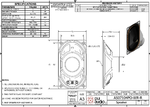
I guess I checked it once but I am not sure . Speaker P/N is : AS07104PO-WR-R from PUI Audio Inc.
speaker.PNG

- - - Updated - - -

Also from the data sheet:

" In order eliminate "clicks and pops", all capacitors must be discharged before turn-on. Rapidly switching VDD may
not allow the capacitors to fully discharge, which may cause "clicks and pops".
There is a relationship between the value of CIN and CBYPASS that ensures minimum output transient when power
is applied or the shutdown mode is deactivated. Best performance is achieved by selecting a CBYPASS value that
is greater than twelve times CIN's value."

helps to read it in detail...

Thanks for your help.
Because of my small experience in analog and due to my hastiness I did'nt focused on datasheet information.
Funny thing happens when I post this problem on TI community and an employee of TI answers me nothing about this
peace of info you put and instead he says if 4.7K ohm works for you so do it.

- - - Updated - - -

perhaps you should connect a diode from pins 4 & 7 to the Vcc (two diodes, kathode to Vcc) this will return the charge on the caps to the Vcc at power down. I note the IC is supposed to take care of clicks and pops in the speakers at power up, due to the 470uF caps, but perhaps it is not so good for short power interruptions as you are suggesting, certainly putting 4k7 in parallel with the speakers should have no noticeable effect, perhaps you are putting them on the other side?

Resistors were placed in PCB. What do you mean "on the other side" ?

Audio_Amp_Top.PNG
Audio_Amp_Bottom.PNG
 

I probe negative pin of the capacitor and it was about -10V and it slowly reach to zero.
Impossible. Nothing in your circuit will have a negative voltage because there is no negative power supply voltage.
The black lead of your multimeter always connects to the circuit ground and the negative wire of each output capacitor also connects to the circuit ground through the speakers. Then the voltage is zero. The positive wire of each output capacitor is probably at half the positive supply voltage then that voltage drops when the power supply is turned off.
 

on the other side means the amp side of the cap, not the speaker side, putting the 4k7 on the amp side may help with your issue, putting on the spkr side side won't change anything, assuming your speakers are tin the range 4 - 8 ohms...
 

Impossible. Nothing in your circuit will have a negative voltage because there is no negative power supply voltage.
The black lead of your multimeter always connects to the circuit ground and the negative wire of each output capacitor also connects to the circuit ground through the speakers. Then the voltage is zero. The positive wire of each output capacitor is probably at half the positive supply voltage then that voltage drops when the power supply is turned off.

suppose positive polarity of the capacitor be at zero voltage then if you have charge in the capacitor then negative polarity of capacitor will be at negative voltage
even if you have not have negative supply in your circuit.
I probe it with scope and it was negative.
 

Hi,

This all tells that there is an issue with your speakers or the connection.
With the connected speaker the negative voltage will exist only for milliseconds.

It seems like there is a relay, any other switching device, diode or capacitor in series with the speaker. Or your measurement is wrong.
What DC value does the scope show at normal operation?

Klaus

After transient moment DC level is zero and then speakers are fine.
 

Hi,

-10V with a 12V supply? .. I maximally expect -6V...with an immediate plop. --> this is the speaker voltage.

about -10V and it slowly reach to zero.
Slowly... this isnot a good description.
We technicians like values.
Some may find milliseconds "fast", sone may find them "slow".

--> Please try to give more detailed informations. Like a scope picture...with the timing setting and the gain setting.

Klaus
 

Hi,

-10V with a 12V supply? .. I maximally expect -6V...with an immediate plop. --> this is the speaker voltage.


Slowly... this isnot a good description.
We technicians like values.
Some may find milliseconds "fast", sone may find them "slow".

--> Please try to give more detailed informations. Like a scope picture...with the timing setting and the gain setting.

Klaus

Thanks for your support.

I said in last posts that it takes about 2 minutes to settle down to zero if i use 100k resistor but
with 4.7k it settle down faster , about 10 seconds.

One of the problem is the pop & click after this long delay . As said in datasheet of the amplifier ,
more delay in start-up results in less pop & click noise but in this situation it is very load even
if it delays about 2 minutes.
 

suppose positive polarity of the capacitor be at zero voltage then if you have charge in the capacitor then negative polarity of capacitor will be at negative voltage
even if you have not have negative supply in your circuit.
I probe it with scope and it was negative.
But the common wire (ground wire) of your 'scope is connected to the circuit's 0V (ground) and the speaker connects the (-) wire of the capacitor also to the circuit's 0V (ground) then the 'scope will show zero.
If the (+) wire of the capacitor is at a positive voltage then its (-) wire is still connected to 0V (ground) through the speaker.

If the capacitor is charged and you connect your 'scope to its (-) wire (without the speaker connected) then connect the capacitor's (+) wire to 0V (ground), the 'scope will show the negative voltage.
That is why we ask if the speaker is not connected.

The LM4952 stereo amplifier is class-AB so with a +12V supply its output pins are about +6V and the datasheet says the bypass pin is also at "half the supply voltage". Then each output capacitor has 6V across it.

Thanks for your response .
I think you are right . I checked it with other resistor values and it react randomly and i find out
resistor may not have any relation to the problem . I must trace more .

I can say the fact is :

With power reset there is a delay about 2 minutes to speakers works again and this follows with a loud "pop & click".

May be i should consider the discharge scheme you said earlier with diodes.

Thanks.
 

Status
Not open for further replies.

Similar threads

Part and Inventory Search

Welcome to EDABoard.com

Sponsor

Back
Top