Continue to Site

Welcome to EDAboard.com

Welcome to our site! EDAboard.com is an international Electronics Discussion Forum focused on EDA software, circuits, schematics, books, theory, papers, asic, pld, 8051, DSP, Network, RF, Analog Design, PCB, Service Manuals... and a whole lot more! To participate you need to register. Registration is free. Click here to register now.

[SOLVED] Audio output from Arduino not working

Status
Not open for further replies.

fm101

Member level 5
Joined
Apr 13, 2020
Messages
81
Helped
1
Reputation
2
Reaction score
4
Trophy points
18
Activity points
591
hi,

I followed the tutorial here
exactly and the code is provided below but the audio output from speaker is like cracking sound white noise only. I have used BD135 as the second transistor and used 4.7k and 2.2k ohm resistors for the R-2R DAC.
The circuit and sound produced is as shown the video below.


the arduino code is attached because it was too long to post here(due to audio sample).


can anybody tell me why is the sound like that and what i should do?


thanks
 

Attachments

  • audioplay.txt
    64.8 KB · Views: 117

Hi,

show your schematic.
show a photo of your wiring.
and show your R-2R ladder ... in detail so we can see the wiring as well as the resistor values.

Klaus
 

hi,
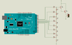
the schematic and picture are below. the audio output can heard in video i posted earlier.


audard.jpg


audard1.jpg

audard.jpg
 

Hi,

I can not see which wire from the arduino goes to which resistor of the R-2R ladder.
So maybe it´s correct, maybe not.

The amplifier is really bad. It causes DC to go to the speaker. Usually the speaker can´t handle this, in worst case it´s coil burns.
It causes extremely high distortion because everything below 1.3V ladder ouput is ingored...this is almost 1/3 of the total signal range.

Every tiny audio amplifier will be better. You will also see the DC suppression (capacitor) in the signal path.

The speaker itself is in no good condition. Are you sure it´s working properly?

Klaus
 

hello,

Wiring photo is not enough clear to see the position of BD135.. ( front or back)
Chek if you don't reverse the BD135 NPN SOT32
pin 1 base
pin 3 emitter
pin2 in the midle = collector
 

hi,
- the R-2R ladder should be good because i previously output sine wave through it and the wiring is good
- i noticed about the dc into speaker and i first tried using the capacitor but this did not work and from the video tutorial he got the audio from the speaker so i wanted to try it out
- i think i got high distortion but don't know how to solve
- i tried amplifier(LM358) with capacitor in signal path but audio output is same
- the speaker though looks bad is good, i got audio output using PCM method and playing music directly

any hints on what i can try? is the audio sample code good?
--- Updated ---

hello,

Wiring photo is not enough clear to see the position of BD135.. ( front or back)
Chek if you don't reverse the BD135 NPN SOT32
pin 1 base
pin 3 emitter
pin2 in the midle = collector
the pin 1 is emitter
 

Hi,

I just reviewd your code.
I guess I found the error:
"delayMicroseconds" is within the "IF". but it needs to be outside.

Klaus
 

    fm101

    Points: 2
    Helpful Answer Positive Rating
Output at the join of R14 R15 ranges from 0 to 5V. Try connecting it directly to one speaker terminal, and the other speaker terminal to 2.5 V. This provides proper AC to the speaker at a safe level. The purpose is to hear sound directly without sending it through an amplifier.

Current shall only be a couple mA. If volume is too soft then try reducing all ohm values in your R2R network.
 

hello,

you can delete the last 133 lines of the sample file
because only 0x7F value is repetead..

the pin 1 is emitter

it is not this case on this document ..
 

Attachments

  • Capture.JPG
    Capture.JPG
    47.3 KB · Views: 122

The DAC isn't the real problem here. Given the correct digital output it will produce a good analog output.
The amplifier is where the problem lies. It has no voltage gain and needs at least 1.2V of signal from the DAC resistors before it even starts to pass current through the loudspeaker. Even then, the lower volume levels will be distorted because the amplifier can't run in class A mode.

The 'dirty' fix is to add a resistor from the base to collector of Q1 so it is forced to conduct some current all the time. That would fix the distortion but be very inefficient.
The simplest 'good' fix is to forget Q1 and Q2 altogether (they will NEVER work as a quality amplifier) and connect the junction of R14 and R15 through a capacitor (100nF will do) to a LM386 or similar amplifier. That gives you a lot more volume for a lot less current and,withing the limitations of the LM386, much higher quality sound.

Brian.
 

Hi,

I just reviewd your code.
I guess I found the error:
"delayMicroseconds" is within the "IF". but it needs to be outside.

Klaus
hi,
this was indeed a mistake, i fixed this and got audio output that is bit better but still the audio is not recognizable.

after correcting the code, i got the following audio output. but still the audio is highly distorted and not recognizable.

**broken link removed**
--- Updated ---

Output at the join of R14 R15 ranges from 0 to 5V. Try connecting it directly to one speaker terminal, and the other speaker terminal to 2.5 V. This provides proper AC to the speaker at a safe level. The purpose is to hear sound directly without sending it through an amplifier.

Current shall only be a couple mA. If volume is too soft then try reducing all ohm values in your R2R network.
hi,
i tired this, there was on audio at all

The DAC isn't the real problem here. Given the correct digital output it will produce a good analog output.
The amplifier is where the problem lies. It has no voltage gain and needs at least 1.2V of signal from the DAC resistors before it even starts to pass current through the loudspeaker. Even then, the lower volume levels will be distorted because the amplifier can't run in class A mode.

The 'dirty' fix is to add a resistor from the base to collector of Q1 so it is forced to conduct some current all the time. That would fix the distortion but be very inefficient.
The simplest 'good' fix is to forget Q1 and Q2 altogether (they will NEVER work as a quality amplifier) and connect the junction of R14 and R15 through a capacitor (100nF will do) to a LM386 or similar amplifier. That gives you a lot more volume for a lot less current and,withing the limitations of the LM386, much higher quality sound.

Brian.
hi,
i tired your advice as well, using resistor between the base and collector reduced the sound level but distortion i don't know, also tired LM386, the same output as using the transistor

i think the code is working, R-2R ladder should be working with 2.2k and 4.7kohm, there is distortion in the audio i think because clearly there is audio as can be heard from the last posted video but is distorted...
--- Updated ---

hi,
thanks all, its working now

idk but at first i had first used portC and got no result, then i later changed to portA, same thing was obtained, later after changing the code and using portA i still got distorsion and when i just changed the port from portA to back to port C, the audio is recognizable.
 
Last edited:

Status
Not open for further replies.

Part and Inventory Search

Welcome to EDABoard.com

Sponsor

Back
Top