Continue to Site

Welcome to EDAboard.com

Welcome to our site! EDAboard.com is an international Electronics Discussion Forum focused on EDA software, circuits, schematics, books, theory, papers, asic, pld, 8051, DSP, Network, RF, Analog Design, PCB, Service Manuals... and a whole lot more! To participate you need to register. Registration is free. Click here to register now.

Audio Circuit Problem

Status
Not open for further replies.
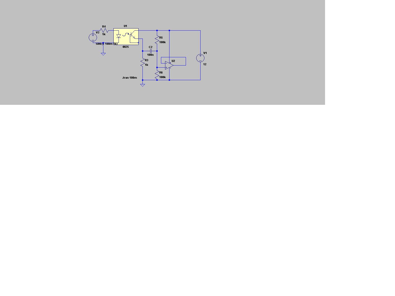
My simple circuit has a load for the photo-transistor which has some gain. It is buffered by an emitter-follower that drives the RadioShack amplified speaker.
 

Thanks again for the suggestions, I'll try them when I go to the lab today.

The reason I'm doing a project like this, while having very little knowledge about circuits, is that I'm a physics major working on a senior project. The project was my advisor's idea; I had no idea how much circuit work it would be. I've taken one basic class as an introduction to circuits, no more. I can solve the Shrodinger equation like a champ, but my exposure to circuitry is limited.

Audioguru, the output of your circuit is for the 9V speaker/amp from Radioshack right, not an 8-ohm speaker?
 

My transistor circuit cannot drive a speaker. It drives a power amplifier like the amplified speaker from RadioShack.
 

You possibly need more gain. With your physical background, you should be able to calculate the expectable signal output,
either in terms of light intensity change or AC photo current.
 

The first circuit without proper biasing worked when fed to a laptop computer.
The laser beam is very strong.
So my circuit should feed a very sensitive RadioShack amplified speaker even better.
 

I built the following today:

circuit-1.jpg


The speaker produced some static while I connected the batteries, then went quiet once everything was connected. The circuit is still not passing the signal at all.
 

The circuit can't work, because the 741 +ve input is floating. (Unlike a LM386, an OP has no internal bias network).
Why don't you refer to known working amplifier circuits from text books and manufacturer application notes?
 

Your speaker in the diagram is still not connected properly. It should have a DC blocking capacitor in series with it. Put the 250uf cap in series with the speaker and put a 47nF cap in series with the 10 ohm resistor.
Don't you have a scope available. It would be really useful in this sort of situation , as you can see when the signal is getting "lost".
 

How is the 741 input floating? I must be missing something.

As for using manufacturer notes, that's exactly what this circuit is from. I put a 9v bias across the detector, set the emitter as the input to a Buffer Op-Amp configuration (from my text book), then took the output from the Op-Amp as the input to the basic 200-gain configuration of the LM381 (from the manufacturer specifications). I'm not winging it with this circuit, I'm just putting the components together like Lego's from what my text and the manufacturer notes say.

Neddie: Looks like I drew the picture wrong. The 250 uF is in series with the speaker in my circuit, sorry about the mistake.
 

Provide some sort of "load" for the emmiter of your opto-transistor. Put say a 100K resistor from the emitter to GND.
 

neddie said:
Provide some sort of "load" for the emmiter of your opto-transistor. Put say a 100K resistor from the emitter to GND.

Ok, I see. "Pull Up" or "Pull Down" configuration for that resistor?
 

The input impedance of the opamp (+) in this configuration is very high , so the
emitter of your opto is "floating" and will end up sitting at a little under 9V(the opwer supply rail).The output of the opto is also like a current source , so it needs a resistor to generate the voltage. Also check the LM386 speaker connection. It was incorrect earlier.
 

A phototransistor is an NPN type. Its collector is connected to a positive voltage. Its emitter is usually connected to ground and it has a high resistance from its collector to the positive supply voltage so that it has a high voltage gain.
But you connected the emitter of your phototransistor as its output then it has no voltage gain. It needs a load resistor.

The input of the opamp needs a bias resistor and a coupling capacitor.
Your opamp is just a follower with no voltage gain like a piece of wire. You could have connected it so it has a lot of voltage gain.
You could have biased the opamp so it operates from a single 9V battery.

Your LM386 power amplifier has many things wrong.
 

I built the following:

circuit-2.jpg


I got some static, and tapping on the reflective surface yielded some wierd noises out of the speaker, but again, no voice. Nothing got hot, though. Am I still missing something important?
 

Maybe you must adjust the current in the photo-transistor so it is not saturated and it is not cutoff.
If the laser beam is too bright then the photo-transistor will be saturated and its emitter load resistor value must be reduced.

Why is the photo-transistor a follower without any voltage gain? If it is a common-emitter transistor like in my schematic then it could have lots of voltage gain and the noisy 741 opamp won't be needed.
 

You're referring to the transistor amplifier circuit you posted earlier, correct?

Will that circuit drive the LM386, or do I have to use the 9v amplified speaker from radioshack with that?
 

Nirodha said:
You're referring to the transistor amplifier circuit you posted earlier, correct?

Will that circuit drive the LM386, or do I have to use the 9V amplified speaker from radioshack with that?

The amplified speaker from RadioShack is simply an LM386 IC plus a transistor at its input to increase the input impedance.

I didn't post a transistor amplifier. i used the photo-transistor as a common emitter transistor so it is an amplifier. The emitter-follower transistor at its output is not an amplifier, it simply reduces the output impedance.
 

I sugest you to use the circuit that neddie drawn and put your LM386 connected to the opamp's output, than you connect a capacitor to the LM386 output and your speaker in series with it. Simple. It isn't the better way to do this, but will work.
If you see the LM386, there's always a capacitor in series with the speaker. The main reason for this is to block the DC current to flow through the speaker. In your case the DC current don't carry any information, just overheat your LM386.
neddie said:
 
Last edited by a moderator:

Status
Not open for further replies.

Similar threads

Part and Inventory Search

Welcome to EDABoard.com

Sponsor

Back
Top