Continue to Site

Welcome to EDAboard.com

Welcome to our site! EDAboard.com is an international Electronics Discussion Forum focused on EDA software, circuits, schematics, books, theory, papers, asic, pld, 8051, DSP, Network, RF, Analog Design, PCB, Service Manuals... and a whole lot more! To participate you need to register. Registration is free. Click here to register now.

[SOLVED] Asymmetric stripline differential trace capacitance

Status
Not open for further replies.

Almog Hacham

Newbie level 3
Newbie level 3
Joined
Nov 11, 2013
Messages
4
Helped
0
Reputation
0
Reaction score
0
Trophy points
1
Visit site
Activity points
24
Hi all,

I'm using asymmetric stripline for differentail traces and I want to calculate the capacitance...

The stack-up is as below:
t = 0.7 mil
w = 4 mil
s = 9 mil
h1 = 4 mil
h2 = 5 mil
Er = 3.8
Length = 15 cm ~= 600 mil

There is someone who know how to calculate the capacitance please?


Thanks a lot,
Almog
 

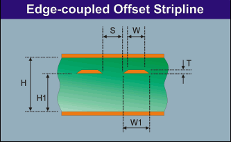
Geometry like this?

4633157400_1384161715.gif
 

Yes, but not exactly.
In my case, w = w1.

In this geometry:
w = 4 mil
s = 9 mil
t = 0.7 mil
H1 = 5 mil
H-H1-t = 4 mil --> H = 9.7 mil


Do you have a calculator for this geometry?


Almog
 

The shape of a real PCB trace will be most likely trapezodial, in so far the model is accounting the facts for better accuracy. But w = w1 is possible of course.

You get 94.8 ohms differential impedance and 1.742 pF/inch.

15 cm corresponds to 6" respectively 6000 mils, by the way.
 
I found some calculators that present 3.486 pF/inch (but it seems to be characteristic capacitance).

From what you sent (1.742 pF/inch) - it's looks like i have to divide the char capacitance by 2 to get the differential load capacitance caused by the traces?
 

1.7 pf/inch is differential capacitance, it's a plausible value for 95 ohm differential pair.
 

    V

    Points: 2
    Helpful Answer Positive Rating
Status
Not open for further replies.

Part and Inventory Search

Welcome to EDABoard.com

Sponsor

Back
Top